Slot array-based beam-pointing two-dimensional controllable holographic antenna and control method thereof

A technology of beam pointing and holographic antennas, which is applied to antenna arrays powered on independently, antenna combinations with different interactions, antennas, etc., can solve the problem of inability to achieve simultaneous deflection of azimuth and elevation angles, and limited application scenarios of one-dimensional beam scanning, etc. problem, to achieve the effect of simple structure, high gain and large scanning range

Inactive Publication Date: 2019-07-19
UNIV OF ELECTRONICS SCI & TECH OF CHINA
View PDF1 Cites 14 Cited by
  • Summary
  • Abstract
  • Description
  • Claims
  • Application Information

AI Technical Summary

Problems solved by technology

However, the application scenarios of one-dimensional beam scanning are very limited, and it is impossible to achieve simultaneous deflection of azimuth and elevation angles
For two-dimensional beam scanning antennas, R. Guzmán-Quirós et al. proposed a FP resonant cavity antenna based on EBG structure in the literature (R.Guzmán-Quirós, A.R.Weily, etc, A Fabry–Pérot Antenna With Two -DimensionalElectronic Beam Scanning, IEEE transactions on antennas and propagation, 2016,64(4):1536-1541), but its disadvantage is that it can only realize beam scanning at several fixed azimuth angles, and can only achieve ±15° small area scan

Method used


Image

  • Slot array-based beam-pointing two-dimensional controllable holographic antenna and control method thereof
  • Slot array-based beam-pointing two-dimensional controllable holographic antenna and control method thereof
  • Slot array-based beam-pointing two-dimensional controllable holographic antenna and control method thereof

Examples


Embodiment Construction

[0031] In order to make the purpose, technical solution and advantages of the present invention clearer, the present invention will be further described in detail below in conjunction with the implementation methods and accompanying drawings.

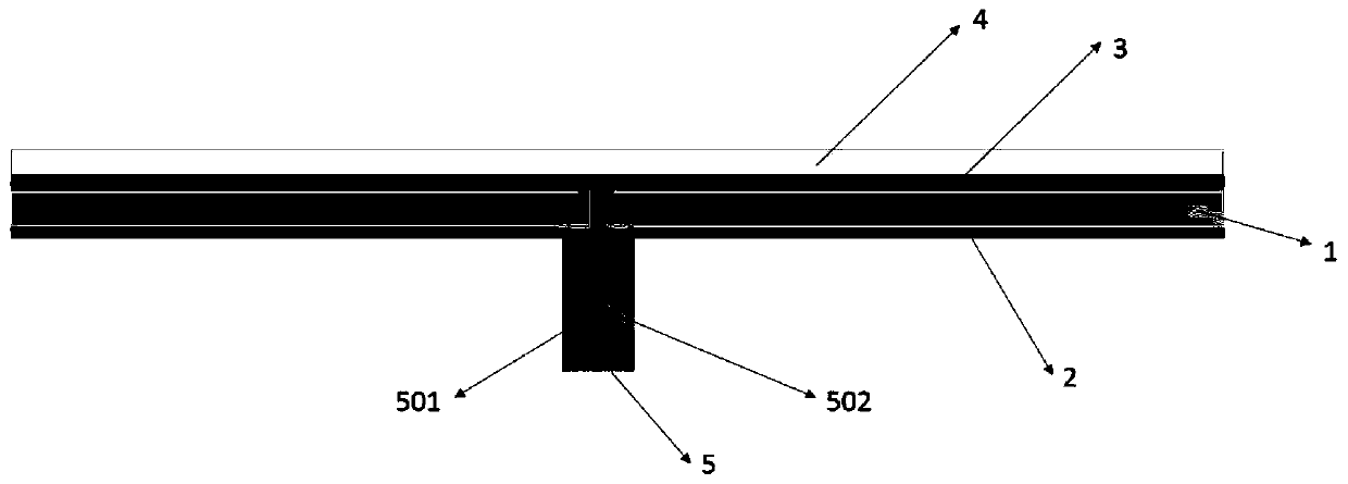
[0032] Such as figure 1 As shown, this embodiment provides a two-dimensional adjustable beam holographic antenna based on a slot array, including a first dielectric substrate 1, a first metal plate 2 located on the lower surface of the first dielectric substrate, and a metal plate located on the upper surface of the first dielectric substrate. The second metal plate 3 , the second dielectric substrate 4 and the power feeding structure 5 located on the upper surface of the second metal plate 3 . Wherein, the feed structure 5 is an SMA (Sub-Miniature-A) connector, the metal shell 501 of the SMA connector is connected to the first metal plate 2, and the inner core probe 502 of the SMA connector is connected to the second metal plate 3, and...


PUM


Abstract

The invention provides a beam-pointing two-dimensional controllable holographic antenna and a control method thereof, and belongs to the technical field of holographic antennas. According to the holographic antenna disclosed by the invention, a novel holographic structure is constructed, namely, a regular slot array is arranged on a second metal plate, and a radio-frequency switch is arranged in the center of each array unit and is used for leaky wave radiation. By applying an FPGA control circuit and a direct-current bias network arranged on the upper surface of a second dielectric substrate,different direct-current bias voltages can be applied to the positive and negative electrodes of each radio-frequency switch so as to control the turn-on or turn-off of the radio-frequency switch. The holographic antenna has the advantages of being simple in structure and low in cost; any beam pointing can be easily realized; and scanning of wave beams on a pitch angle and an azimuth angle is realized, and a scanning range of + / -65 degrees can be reached.

Description

technical field [0001] The invention belongs to the technical field of holographic antennas, and in particular relates to a holographic antenna with two-dimensional controllable beam pointing and a control method thereof. Background technique [0002] The principle of holography comes from the field of optics. It refers to the technology of using some photosensitive materials to record the interference field formed by the interference of the reference wave and the target wave to obtain the interference surface, and then irradiating the interference surface with the reference wave to invert the target wave. The film of the traditional photography technology can only record the light intensity information, but the holographic technology can record the intensity and phase information of the object light at the same time, so it can realize the three-dimensional reproduction of the object image. [0003] The research on applying the holographic principle to the microwave band has...

Claims


Application Information

Patent Timeline
Patent Type & Authority Applications(China)
IPC IPC(8): H01Q21/06H01Q21/29H01Q3/24H01Q1/50H01Q1/38
CPCH01Q1/38H01Q1/50H01Q3/247H01Q21/064H01Q21/293
Inventor 梁锋谢雨希刘琦汪相如王秉中
Owner UNIV OF ELECTRONICS SCI & TECH OF CHINA
Why Eureka
Try Eureka