Air conditioner for vehicle

A technology for air-conditioning devices and vehicles, which is applied to vehicle parts, transportation and packaging, air handling equipment, etc., and can solve problems such as poor lubricity of compressors

Active Publication Date: 2022-07-08
DENSO CORP
View PDF8 Cites 0 Cited by
  • Summary
  • Abstract
  • Description
  • Claims
  • Application Information

AI Technical Summary

Problems solved by technology

[0017] Therefore, according to the research of the inventors of the present application, in the second dehumidification and heating mode, the flow rate of the refrigerant flowing in the outdoor heat exchanger is reduced, thus causing the refrigerating machine oil not to flow out of the outdoor heat exchanger but stored in the outdoor heat exchanger. For exchangers, there are cases where the lubricity of the compressor tends to deteriorate

Method used


Image

  • Air conditioner for vehicle
  • Air conditioner for vehicle
  • Air conditioner for vehicle

Examples


Embodiment Construction

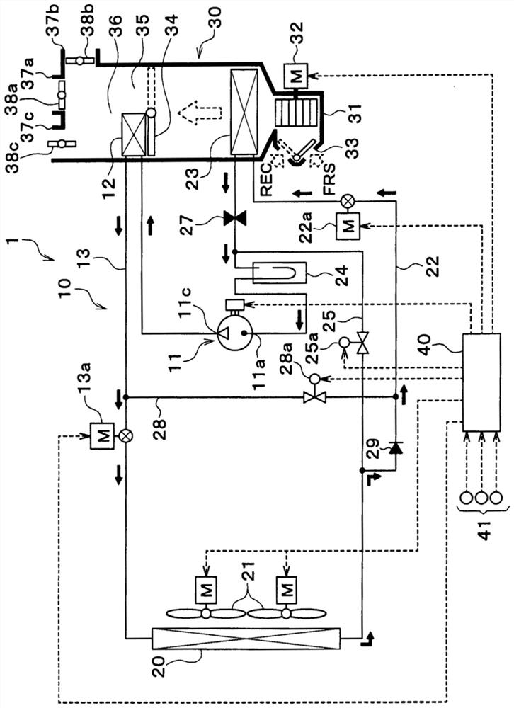
[0030] Hereinafter, embodiments will be described with reference to the drawings. In the present embodiment, the heat pump cycle 10 is applied to the vehicle air conditioner 1 of the hybrid vehicle that obtains the driving force for running from an engine (in other words, an internal combustion engine) and an electric motor for running. The heat pump cycle 10 is a vapor compression refrigeration cycle.

[0031] In the vehicle air conditioner 1, the heat pump cycle 10 functions to cool or heat the air blown into the vehicle interior. Therefore, the air-conditioning target space of the present embodiment is a space in the vehicle interior, and the heat exchange target fluid of the present embodiment is air blown into the vehicle interior.

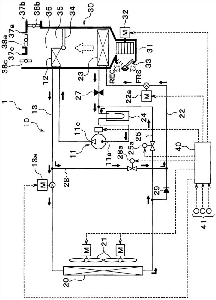
[0032] The heat pump cycle 10 is configured to be able to figure 1 cooling mode shown, figure 1 Shown in series dehumidification and heating mode, figure 2 Parallel dehumidification and heating mode as shown, or image 3 The refrigerant...


PUM


Abstract

A vehicle air conditioner includes a compressor (11), a radiator (12), an outdoor heat exchanger (20), an evaporator (23), a first decompression unit (13a), a second decompression unit (22a), a switch parts (25a, 28a), and a control part (40). The radiator exchanges heat between the refrigerant discharged from the compressor and the air blown into the vehicle interior. The outdoor heat exchanger exchanges heat between the refrigerant flowing out of the radiator and the outside air. The evaporator exchanges heat between the refrigerant flowing out of the outdoor heat exchanger and the air flowing into the radiator. The switching unit switches between the series dehumidification and heating mode and the parallel dehumidification and heating mode. In the series dehumidification and heating mode, the outdoor heat exchanger and the evaporator are connected in series in the flow direction of the refrigerant. In the parallel dehumidification and heating mode , the outdoor heat exchanger and the evaporator are connected in parallel on the flow of refrigerant. In the parallel dehumidification and heating mode, when it is determined that the amount of refrigerating machine oil flowing from the outdoor heat exchanger to the compressor is insufficient, the control unit controls the switching unit to switch to the series dehumidification and heating mode.

Description

[0001] Cross-referencing of related applications [0002] The present application uses Japanese Patent Application No. 2016-228999 for which it applied on November 25, 2016, the contents of which are incorporated herein by reference. technical field [0003] The present invention relates to a vehicle air conditioner having a dehumidification and heating mode. Background technique [0004] Patent Document 1 describes a refrigeration cycle apparatus including a compressor, an indoor condenser, a first expansion valve, an outdoor heat exchanger, a second expansion valve, an indoor evaporator, and the like. [0005] In Patent Document 1, the first dehumidification and heating mode and the second dehumidification and heating mode can be appropriately switched according to the operating environment of the vehicle air conditioner. [0006] In the first dehumidification and heating mode, the outdoor heat exchanger and the indoor evaporator are connected in series with respect to th...

Claims


Application Information

Patent Timeline
Patent Type & Authority Patents(China)
IPC IPC(8): B60H1/22B60H1/32F25B1/00F25B5/00F25B29/00
CPCF25B1/00F25B5/00F25B29/00B60H1/00921B60H2001/00949B60H1/00885B60H1/3214B60H2001/3242B60H2001/3285B60H2001/3283B60H3/024B60H1/22B60H1/32F25B31/002F25B31/004F25B29/003
Inventor 久户辰朗小林宽幸远藤义治
Owner DENSO CORP
Why Eureka
Try Eureka