Fuel injector arrangement

A fuel injector and assembly technology, which can be applied to fuel injection devices, special fuel injection devices, fuel injection devices with oil reservoirs, etc., can solve problems such as consumption

Active Publication Date: 2019-07-19
L'ORANGE GMBH
View PDF8 Cites 1 Cited by
  • Summary
  • Abstract
  • Description
  • Claims
  • Application Information

AI Technical Summary

Problems solved by technology

This connection at the shortest possible distance must be adjusted in a complex manner by the injector peripherals
The situation of emergency shut-off is also troublesome, where usually the gas pressure is shut off first, while the control fluid pressure and the closed oil pressure disadvantageously continue to exist

Method used


Image

  • Fuel injector arrangement
  • Fuel injector arrangement
  • Fuel injector arrangement

Examples


Embodiment Construction

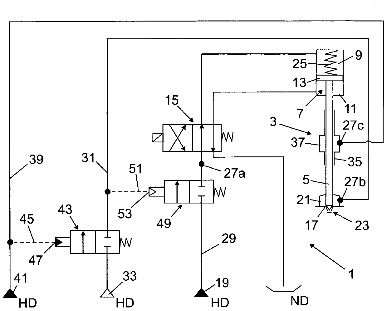
[0036] figure 1 A fuel injector assembly 1 is shown which has, inter alia, a fuel injector 3 which is provided for injecting gas. The fuel injector 3 comprises at least one gas nozzle valve element 5, preferably also a liquid fuel nozzle valve element (in figure 1 The gas nozzle valve element 5) is shown only by way of example. The fuel injector 3 is preferably a dual-fuel fuel injector, that is to say designed for injecting gas and liquid fuel.

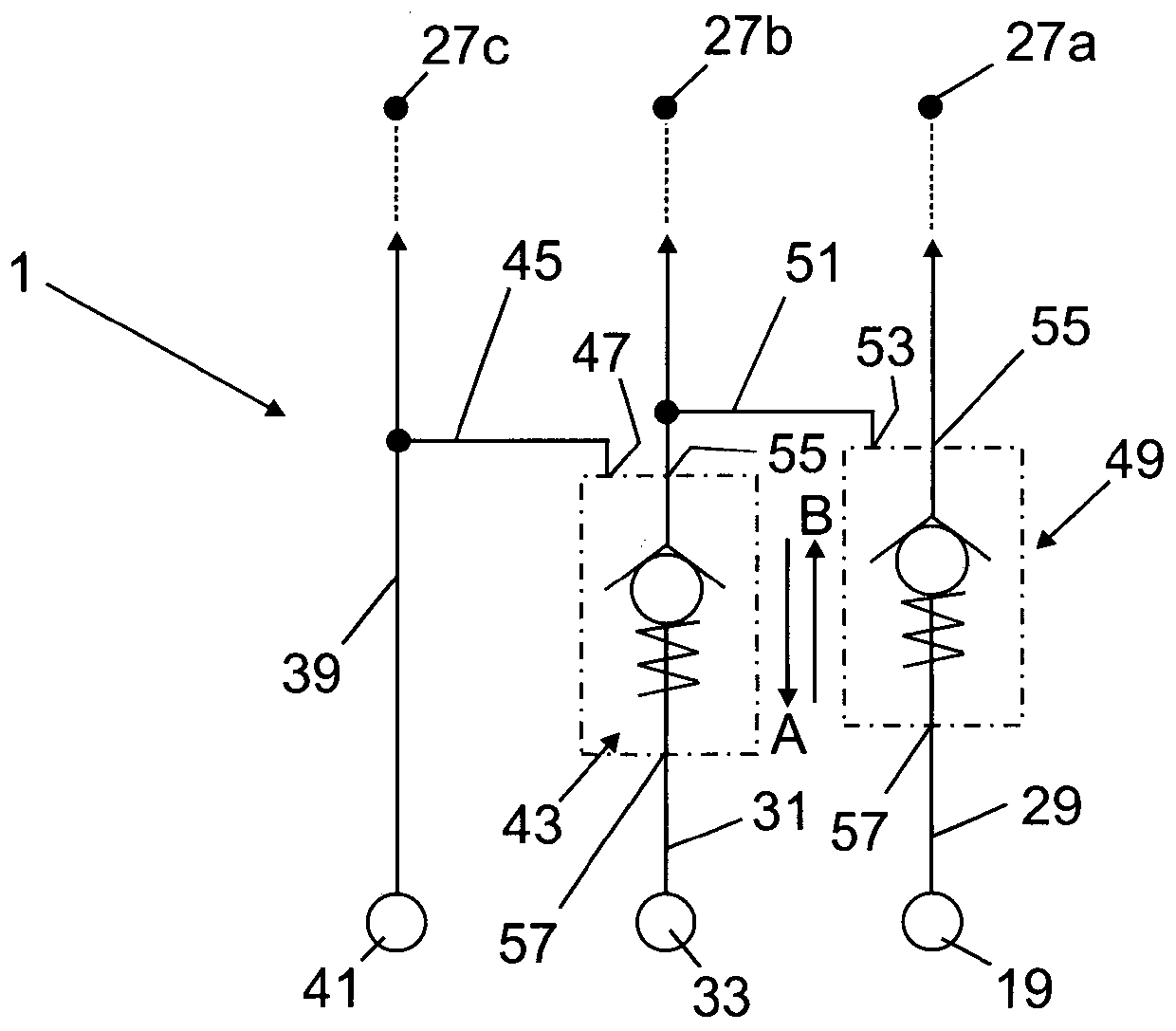
[0037] For controlling the gas nozzle valve element 5, the fuel injector 3 has a piston control assembly 7 comprising a first control chamber 9 and a second control chamber 11 between which the hydraulic reciprocating control of the piston is possible. The piston 13 of the control unit 7 , which is connected to the gas nozzle valve element 5 , that is to say via a corresponding pressure loading and depressurization of the control chambers 9 , 11 by means of the control fluid. In order to direct the control fluid to and from the co...


PUM


Abstract

The invention relates to a fuel injector arrangement (1) comprising a number of fluid supply paths (29, 31, 39), namely a first (29), a second (31) and a third fluid supply path (39). The fuel injector arrangement (1) has a first switching device (43) in the second fluid supply path (31). Said first switching device, controlled by the fluid pressure in the third fluid supply path (39), opens or blocks the second fluid supply path (31). The fuel injector arrangement (1) has a second switching device (49) in the first fluid supply path (29). Said second switching device, controlled by the fluidpressure downstream of the first switching device (43) in the second fluid supply path (31), opens or blocks the first fluid supply path (29).

Description

technical field [0001] The invention relates to a fuel injector assembly according to claim 1 . Background technique [0002] Fuel injector assemblies are known in the prior art which have fuel injectors for discharging gas and which are corresponding gas nozzle valve elements for controlling the fuel injectors, That is, one or more gas nozzle valve elements using a control fluid, such as control oil. In order to avoid unintentional ingress of gas into the control fluid control circuit during gas operation, in particular due to creep paths along the corresponding gas nozzle valve element guide, it is possible to separate the medium or seal at the corresponding gas nozzle valve element guide It is proposed to use a sealing fluid (sealing oil), ie in the region of the sealing fluid seal around the respective gas nozzle valve element (furthermore, other sealing fluid seals can be provided at other locations in the fuel injector). [0003] With regard to operational safety and...

Claims


Application Information

Patent Timeline
Patent Type & Authority Applications(China)
IPC IPC(8): F02M63/00F02M43/04F02M47/02F02M21/02F02D19/06F02D19/10
CPCF02D19/061F02D19/0694F02D19/105F02D41/0025F02D41/0027F02M21/0251F02M21/0263F02M43/04F02M47/027F02M63/0017F02M63/0028F02M63/0043F02M63/0047F02M63/0054Y02T10/30F02M47/046F02M2200/40F02M2200/44
Inventor I·伯杰E·巴罗M·尼切
Owner L'ORANGE GMBH
Why Eureka
Try Eureka