
Multi-viewpoint directional naked eye 3D display

A 3D display and multi-viewpoint technology, applied in the direction of instruments, optical components, optics, etc., can solve the problems of small viewable area, dizziness and crosstalk of the viewer

Inactive Publication Date: 2019-07-23
DONGGUAN CITY TUOPULAISI PHOTOELECTRIC TECH CO LTD
View PDF6 Cites 1 Cited by
  • Summary
  • Abstract
  • Description
  • Claims
  • Application Information

AI Technical Summary

Problems solved by technology

[0003] In the prior art, in order to ensure that the left and right eyes can accurately receive the light beam, the viewer needs to watch at a specific position, otherwise the problem of image crosstalk will occur due to incorrect position; in practical applications, closer adjacent viewpoints Crosstalk is easy to occur between them, which makes the viewer prone to dizziness. Today's directional naked eyes also need to set a large blind area between adjacent viewpoints, which results in a smaller viewing area for the viewer.

Method used


Image

  • Multi-viewpoint directional naked eye 3D display
  • Multi-viewpoint directional naked eye 3D display
  • Multi-viewpoint directional naked eye 3D display

Examples


Embodiment Construction

[0024] The present invention will be described in detail below in conjunction with specific embodiments and accompanying drawings.

[0025] Example.

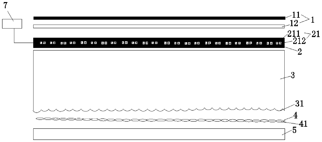
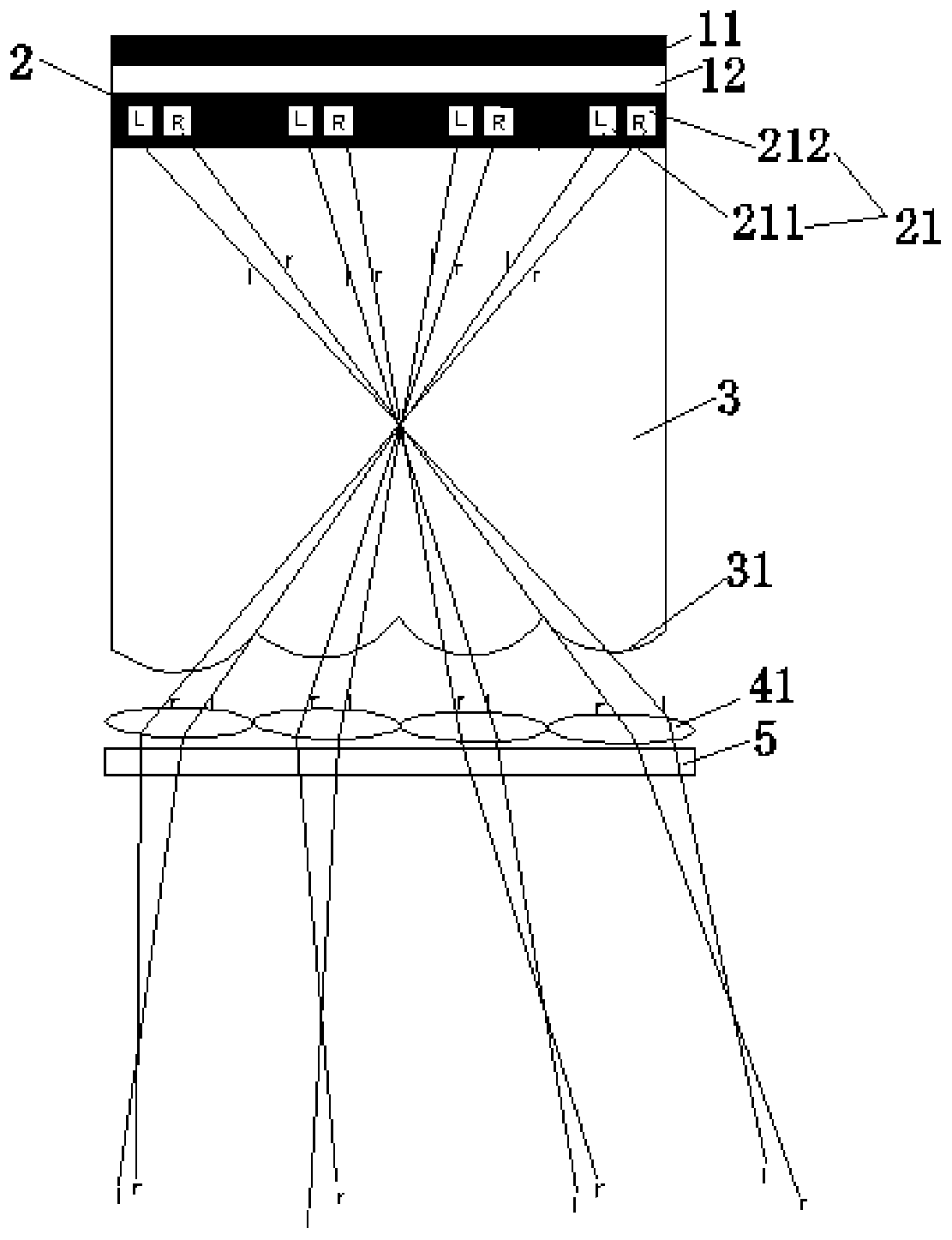
[0026] A multi-viewpoint oriented naked-eye 3D display in this embodiment, figure 2 As shown, it includes a backlight 1, an LCD switch plate 2, and a cylindrical lens plate 3 that are sequentially aligned and bonded from back to front. A convex lens plate 4 is fixed in front of the cylindrical lens plate 3, and a convex lens plate 4 is bonded in front of the The liquid crystal display panel 5 forms a 3D naked-eye display.

[0027] figure 1 As shown, the LCD switch board 2 is provided with several viewpoint units 21, and several viewpoint units 21 are arranged in sequence along the length direction of the LCD switch board 2 board surface, leaving a distance between adjacent viewpoint units 2, and each viewpoint unit 2 One L column LCD unit 211 and one R column LCD unit 212 are included. figure 2 As shown, the L column LCD u...


PUM


Abstract

The invention relates to the technical field of 3D displays, in particular to a multi-viewpoint directional naked eye 3D display. The structure of the multi-viewpoint directional naked eye 3D displaycomprises a backlight source, an LCD switch plate and a cylindrical lens plate, and the backlight source, the LCD switch plate and the cylindrical lens plate are sequentially aligned and attached fromback to front, wherein a convex lens plate is fixedly arranged in front of the cylindrical lens plate, and a liquid crystal display panel is attached in front of the convex lens plate; the LCD switchplate is provided with a plurality of viewpoint units, the plurality of pairs of viewpoint units are sequentially arranged along the length direction of the LCD switch plate, a space is reserved between the adjacent viewpoint units, each viewpoint unit comprises an L-column LCD unit and an R-column LCD unit, the L-column LCD unit is positioned on the left side and emits light beams received by the left eye, and the R-column LCD unit is positioned on the right side and emits light beams received by the right eye; the convex lens plate is provided with a plurality of convex lenses, the main optical axis of each convex lens is perpendicular to the plate surface of the cylindrical lens plate, and each convex lens correspondingly receives the light beam of one viewpoint unit.

Description

technical field [0001] The invention relates to the technical field of 3D displays, in particular to a multi-viewpoint oriented naked-eye 3D display. Background technique [0002] Glasses-free 3D display refers to a display that can watch 3D stereo effects without wearing 3D glasses. After using this glasses-free 3D display, viewers wearing glasses do not need to wear two pairs of eyes, which greatly improves the convenience of viewing 3D images. Among the naked-eye 3D displays, there is a kind of directional backlight naked-eye 3D display, and the directional backlight naked-eye 3D display generates a 3D effect by alternately emitting light beams received by the left eye and light beams received by the right eye. [0003] In the prior art, in order to ensure that the left and right eyes can accurately receive the beam, the viewer needs to watch at a specific position, otherwise the problem of image crosstalk will occur due to incorrect position; in practical applications, c...

Claims


Application Information

Patent Timeline
Patent Type & Authority Applications(China)
IPC IPC(8): G02B27/22
CPCG02B30/27
Inventor 陈燕平李幼伟
Owner DONGGUAN CITY TUOPULAISI PHOTOELECTRIC TECH CO LTD
Learn More