Novel inclined projection imaging optical system

A technology of imaging optics and oblique projection, applied in optics, optical components, instruments, etc., can solve the problems of complex process, high cost, difficult application, etc., and achieve the effect of clear imaging

Inactive Publication Date: 2019-07-23
王杰芳
View PDF4 Cites 3 Cited by
  • Summary
  • Abstract
  • Description
  • Claims
  • Application Information

AI Technical Summary

Problems solved by technology

[0004] In order to obtain a clear lighting effect on inclined surfaces, the new welcome lights of the BMW 7 Series sedan innovatively adopted microlens array projection technology to finally achieve clear lighting effects on inclined surfaces, and in 2016 the newly launch

Method used


Image

  • Novel inclined projection imaging optical system
  • Novel inclined projection imaging optical system
  • Novel inclined projection imaging optical system

Examples


Embodiment 1

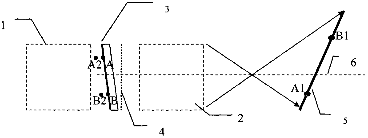
[0025] An oblique projection imaging optical system formed by "obliquely placing the projected image-carrying substrate".

[0026] figure 2 It is the oblique projection imaging optical system constructed in Example 1; in the figure, 1 is the illumination optical system, 2 is the projection imaging optical system, 3 is the projected image and the substrate carrying the projected image, and 4 is the focal plane of the projection imaging optical system , 5 is the projection plane; in this embodiment, the "projected image and the carrier substrate" are placed obliquely, so that the images (such as A point and B point) in different regions on the projected image have different characteristics for the projection imaging optical system. The optical object distance, and then the A1 point and B1 point with different optical image distances of the projection imaging optical system on the projection plane can obtain clear projection imaging. The relationship between the optical object ...

Embodiment 2

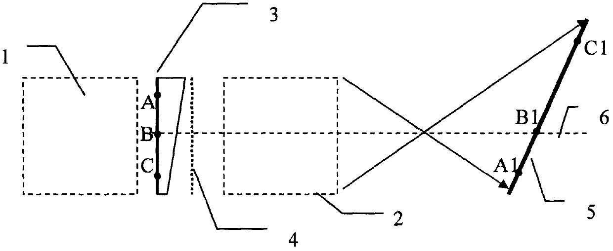
[0030] An oblique projection imaging optical system formed by "adjusting the thickness of the projected image bearing substrate".

[0031] image 3It is the oblique projection imaging optical system constructed in Example 2; in the figure, 1 is the illumination optical system, 2 is the projection imaging optical system, 3 is the projected image and the substrate carrying the projected image, and 4 is the focal plane of the projection imaging optical system , 5 is the projection plane; in this embodiment, the thickness of "the projected image and the carrier substrate" is adjusted, so that the images of different regions on the projected image (such as A point, B point, C point, etc.) The system has different optical object distances, and then clear projection imaging can be obtained on the projection plane relative to A1 point, B1 point, C1 point and other positions of different optical image distances of the projection imaging optical system. Point A and point A1, point B an...

Embodiment 3

[0036] An oblique projection imaging optical system formed by "adjusting the thickness of the projected image bearing substrate on an inclined plane or a stepped surface".

[0037] In embodiment 2, we can make every point in the projected figure obtain good imaging on the inclined plane; but the thickness variation trend of different regions of the substrate carrying the projected image will be very complicated, which is critical for processing and application Very unfavorable.

[0038] A compromise consideration is: we only consider three points with the largest image distance, the smallest image distance, and the average image distance after the projected image is projected, assuming that the points on the projected image corresponding to these three image distance values ​​are AS, BS, CS;

[0039] By designing the rear surface of the substrate carrying the projected image (the front surface carries the projected image) as a slope that is not parallel to the front surface, ...


PUM


Abstract

The invention relates to a novel inclined projection imaging optical system, in particular to a novel optical system capable of enabling different areas of "a projected image" to be projected at different imaging distances. In a traditional projection and imaging optical system, "a projected image" is generally perpendicular to the optical axis of an optical projection system, and is parallel to the focal plane (that is, the projected image surface is parallel to the focal plane or the main surface of the projection system) of the projection optical system, so that the "optical image" formed by projection of the projection optical system is also perpendicular to the optical axis of the optical system. When the projection plane is not perpendicular to the optical axis of the projection optical system (that is, the projection plane is not parallel to the focal plane of the optical system), the system cannot obtain a relatively clear projection effect at the projection plane; and the structure disclosed by the invention can obtain a clear projection effect at different distances from the projection system. The system can be widely applied to vehicle-mounted projection and advertisement projection systems to form new products which can be clearly projected on an inclined projection plane.

Description

technical field [0001] The invention relates to a new type of oblique projection imaging optical system, in particular to an optical system capable of clearly forming a "projected image" on an oblique surface. This technology can be widely used in vehicle warning lamps, vehicle decorative lighting lamps, vehicle welcome lights, advertising projection lamps, interior lighting and decorative lamps and other fields; Background technique [0002] With the improvement of people's living standards, a large number of decorative lights have been promoted and used, among which advertising projection lights and car welcome lights have become industry standard equipment. However, the existing advertising lamps and welcome lamps are all composed of coaxial optical systems, that is, the projected image, the focal plane of the projection optical system, and the image plane of the projection optical system (ie, the projection plane) are all parallel to each other, and the projected image i...

Claims


Application Information

Patent Timeline
IPC IPC(8): G03B21/00G03B21/20G02B13/00
CPCG02B13/00G03B21/00G03B21/20G03B21/208
Inventor 王杰芳
Owner 王杰芳
Why Eureka
Try Eureka