A transmissive array antenna with high stopband rejection and low radar cross-sectional area

An array antenna and suppression technology, which is applied in the direction of antenna, antenna coupling, waveguide horn, etc., to achieve the effect of improving suppression ability, low RCS characteristics, and realizing reduction

Active Publication Date: 2021-06-01
UNIV OF ELECTRONICS SCI & TECH OF CHINA
View PDF0 Cites 0 Cited by
  • Summary
  • Abstract
  • Description
  • Claims
  • Application Information

AI Technical Summary

Problems solved by technology

However, although this kind of transmissive unit can form a transmission passband with a high degree of stopband rejection, it presents a state of total reflection to incident electromagnetic waves outside the working frequency band, making its radar cross-sectional area (RCS) equivalent to that of a large metal floor
On the other hand, although RCS reduction technology has been widely concerned in phased array antennas, there are few reports on RCS reduction technology for transmitted array antennas

Method used


Image

  • A transmissive array antenna with high stopband rejection and low radar cross-sectional area
  • A transmissive array antenna with high stopband rejection and low radar cross-sectional area
  • A transmissive array antenna with high stopband rejection and low radar cross-sectional area

Examples


Embodiment Construction

[0023] The technical solutions of the present invention will be described in detail below in conjunction with the drawings and embodiments, but the protection scope of the present invention is not limited to the embodiments.

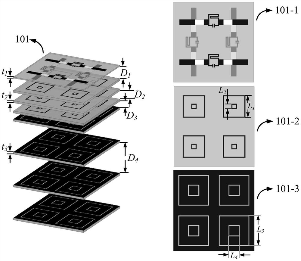
[0024] figure 1 It is a transmission array unit with high stop band suppression and low RCS in the embodiment of the present invention. It is composed of a high stop band suppression transmission array unit, a dual polarization band-pass absorption type frequency selective surface and a high frequency band stop frequency selective surface. Its reasonable arrangement realizes the radiation characteristics of high gain and high stop band rejection and the reduction of RCS;

[0025] In this embodiment 1, t 1 Thickness is 0.25mm, t 2 with t 3The thickness is 0.5mm; D 1 = 3mm, D 2 = 2mm, D 3 = 1 mm, D 4 =7mm; the overall size of the unit is 18mm×18mm; the width of the metal strip in 101-2 is 0.4mm, L 1 = 4L 2 ;The width of the metal groove in 101-3 i...


PUM


Abstract

The invention discloses a transmission array antenna with a high stop band suppression degree and a low radar scattering cross-sectional area. The invention belongs to the field of wireless communication technology and radar technology, and in particular relates to a transmission array antenna enhancing the ability to suppress out-of-band interference signals and reducing the radar scattering cross-sectional area (RCS) and other technologies. The transmission array antenna with high stop band rejection and low RCS proposed by the present invention uses a horn antenna for feeding, and its high stop band transmission unit, high frequency band stop frequency selective surface and dual polarization band pass resistive frequency selective surface are integrated , and by adjusting the corresponding parameters of the unit, the independent control of the transmission characteristics and RCS reduction characteristics is realized. The beneficial effects of the present invention are as follows: 1. A high stopband suppression degree and low RCS transmission array antenna unit structure is proposed; 2. The antenna's ability to suppress out-of-band interference signals is significantly improved; 3. Different structures of low frequency and high frequency are used as dipoles The design of the band-pass resistive frequency selective surface floor realizes the reduction of RCS in ultra-wideband.

Description

technical field [0001] The invention belongs to the field of wireless communication technology and radar technology, and in particular relates to technologies such as enhancing the ability of a transmission array antenna to suppress out-of-band interference signals, reducing the radar cross-sectional area (RCS), and the like. Background technique [0002] The stop band suppression degree is an important index to measure the ability of the communication system to suppress the interference signal. The higher the parameter, the stronger the system's ability to suppress out-of-band interference signals. In most wireless communication systems, the filter is usually directly connected to the input or output port of the antenna. The filter and the antenna, as two large-scale key components, are usually designed independently, but when the filter and the antenna are used in cascade, the impedance will often be mismatched. At this time, it is necessary to introduce an additional ma...

Claims


Application Information

Patent Timeline
Patent Type & Authority Patents(China)
IPC IPC(8): H01Q19/06H01Q15/00H01Q13/02H01Q1/52
CPCH01Q1/52H01Q13/02H01Q15/0006H01Q19/06
Inventor 屈世伟冯鹏雨李小秋杨仕文孙红兵周志鹏
Owner UNIV OF ELECTRONICS SCI & TECH OF CHINA
Why Eureka
Try Eureka