
Water-cooled motor

A technology of water-cooled motors and water-cooled chambers, applied in the direction of electrical components, electromechanical devices, electric components, etc., can solve problems such as damage to the internal circuit of the motor, decline in motor performance indicators, inconvenient motor installation, etc., to improve efficiency, reduce volume, The effect of rapid cooling

Active Publication Date: 2019-07-23
绍兴劲鹰机械制造有限公司
View PDF5 Cites 2 Cited by
  • Summary
  • Abstract
  • Description
  • Claims
  • Application Information

AI Technical Summary

Problems solved by technology

[0002] At present, since the motor will generate a certain amount of heat during energy conversion, it is necessary to dissipate the heat generated by the motor in a timely manner during the operation of the motor, otherwise the motor temperature will be too high, which will lead to a decline in the performance of the motor, and even damage the inside of the motor circuit
[0003] At present, the motor cooling methods on the market are mainly air-cooled and water-cooled. Among them, the water-cooled motor is provided with a cavity on the casing, and then through the water in the cavity, the heat inside the motor is exchanged through the water body. However, During the use of the existing water-cooled motor, it sets the water inlet and outlet structure on the casing of the motor, and then connects an external water tank through a hose, and then sends the water in the water tank back to the cavity through the pump body. However, because the volume of the water tank is relatively large, it takes up a relatively large space, so it is not convenient to install the motor when the motor is installed, and because the water inlet and outlet structure on the motor is protruding from the casing when the motor is installed The outer wall, so when installing the motor, the water inlet and outlet structure will hinder the installation of the motor into the equipment

Method used


Image

  • Water-cooled motor
  • Water-cooled motor
  • Water-cooled motor

Examples


Embodiment Construction

[0035] In order to enable those skilled in the art to better understand the solutions of the present invention, the technical solutions in the embodiments of the present invention will be clearly and completely described below in conjunction with the drawings in the embodiments of the present invention.

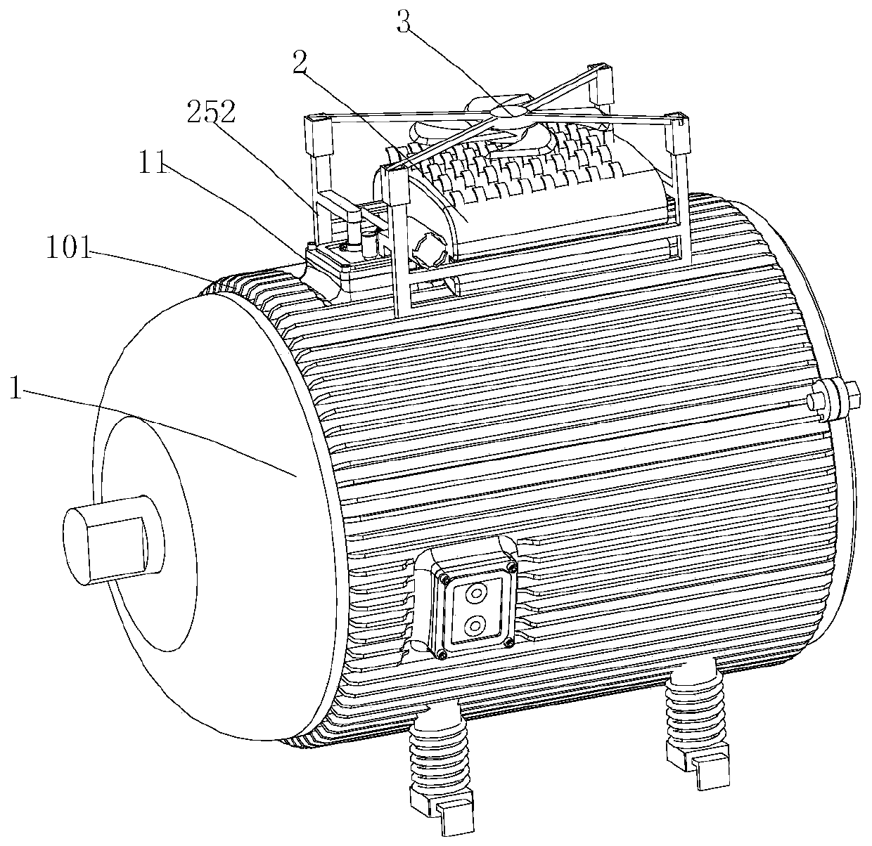
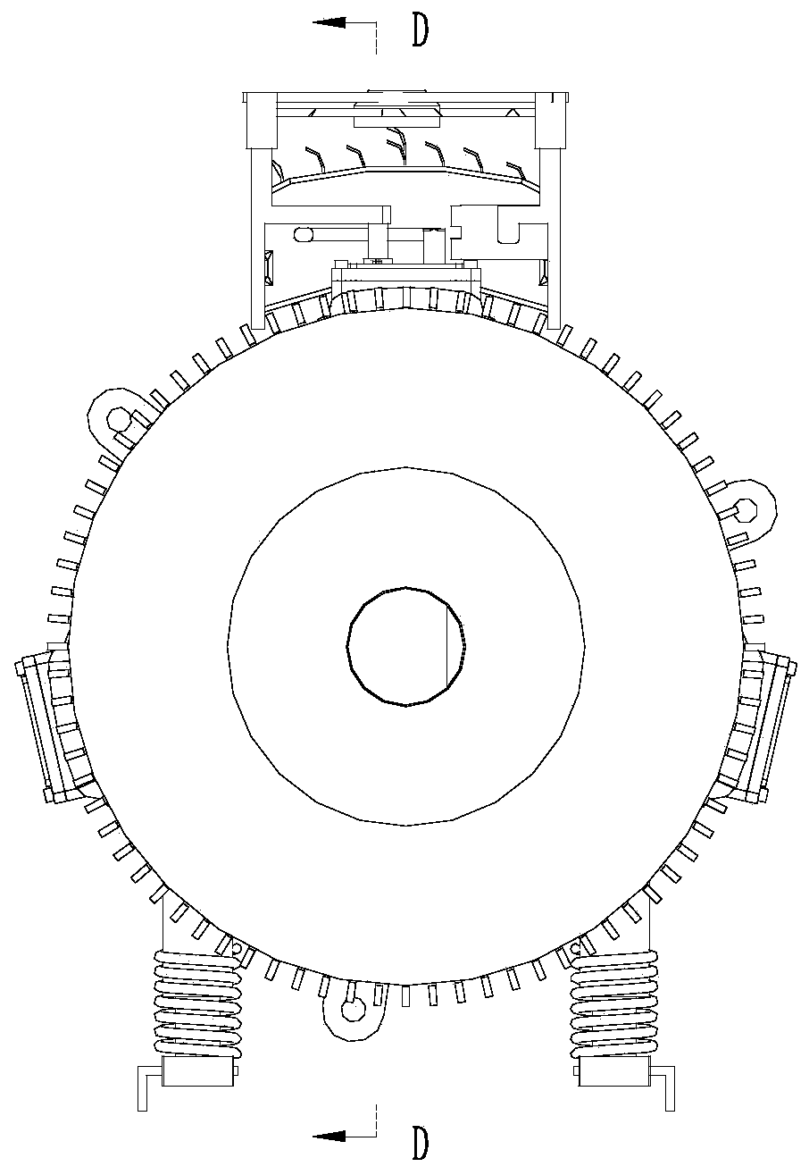
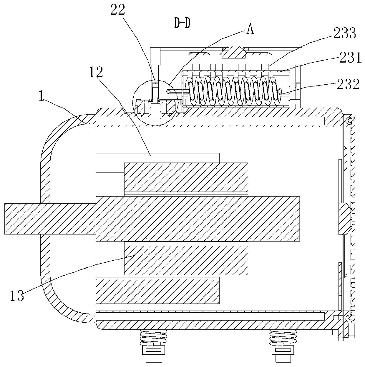
[0036] like Figure 1-12 As shown, a water-cooled motor includes a casing 1, a connecting portion 11, a stator 12, a rotor 13, a circulation device 2 and an air-cooled component 3, wherein the casing 1 is an aluminum casing, and the casing 1 is provided with There is a water-cooling chamber 10, filled with refrigerant in the water-cooling chamber 10, the refrigerant is water, or other existing refrigerants; the stator 12 and the rotor 13 are all arranged in the casing 1, wherein The stator 12 and the rotor 13 are all arranged in the housing 1, which is the same as the stator and rotor of the existing motor, so it is a prior art; the connecting part 11 is formed on the casing ...


PUM


Abstract

The invention discloses a water-cooled motor. The water-cooled motor comprises an enclosure, multiple connecting parts arranged on the enclosure, a stator arranged in the enclosure, a rotor arranged in the enclosure, a circulation device and an air-cooling component, wherein the enclosure is provided with a water-cooling cavity, and the water-cooling cavity is filled with a refrigerant; the circulation device is detachably connected with one of the connecting parts and is used for extracting the refrigerant in the water-cooling cavity to cool the refrigerant; and the air-cooling component is arranged on the circulation device and is used for air-cooling the refrigerant on the circulation device. According to the water-cooled motor, through the arrangement of the multiple connecting parts,during installation of the circulation device, one of the connecting parts can be selected according to need for installation, and therefore the circulation device can have three locations. In this way, motor installation efficiency can be effectively improved, and therefore the motor can adapt to a wider range of and a large quantity of equipment.

Description

technical field [0001] The invention belongs to the technical field of motors, in particular to a water-cooled motor. Background technique [0002] At present, since the motor will generate a certain amount of heat during energy conversion, it is necessary to dissipate the heat generated by the motor in a timely manner during the operation of the motor, otherwise the motor temperature will be too high, which will lead to a decline in the performance of the motor, and even damage the inside of the motor circuit. [0003] At present, the motor cooling methods on the market are mainly air-cooled and water-cooled. Among them, the water-cooled motor is provided with a cavity on the casing, and then through the water passing through the cavity, heat exchange is performed through the heat inside the water body motor, but During the use of the existing water-cooled motor, it sets the water inlet and outlet structure on the casing of the motor, and then connects an external water ta...

Claims


Application Information

Patent Timeline
IPC IPC(8): H02K9/19H02K9/193H02K9/04
CPCH02K9/19H02K9/193H02K9/04H02K5/04H02K5/18
Inventor 陈小标陈玉飞谢百锋陈杰
Owner 绍兴劲鹰机械制造有限公司
Learn More