
A power communication laser scanning device

A laser scanning device, power communication technology, applied in electrical components, electromagnetic wave transmission systems, transmission systems, etc., can solve the problem of low detection efficiency of optical fiber fault sections, and meet the requirements of improving fault detection efficiency and reducing construction accuracy. adaptive effect

Active Publication Date: 2020-06-23
任永辉
View PDF8 Cites 0 Cited by
  • Summary
  • Abstract
  • Description
  • Claims
  • Application Information

AI Technical Summary

Problems solved by technology

[0003] The invention provides a laser scanning device for electric power communication to solve the problem of low detection efficiency of faulty sections of optical fibers at present

Method used


Image

  • A power communication laser scanning device

Examples


Embodiment Construction

[0018] In order to enable those skilled in the art to better understand the technical solutions in the embodiments of the present invention, and to make the above-mentioned purposes, features and advantages of the embodiments of the present invention more obvious and understandable, the following describes the technical solutions in the embodiments of the present invention in conjunction with the accompanying drawings For further detailed explanation.

[0019] In the description of the present invention, unless otherwise specified and limited, it should be noted that the term "connection" should be understood in a broad sense, for example, it can be a mechanical connection or an electrical connection, or it can be the internal communication of two elements, it can be Directly connected or indirectly connected through an intermediary, those skilled in the art can understand the specific meanings of the above terms according to specific situations.

[0020] see figure 1 , is a ...


PUM


Abstract

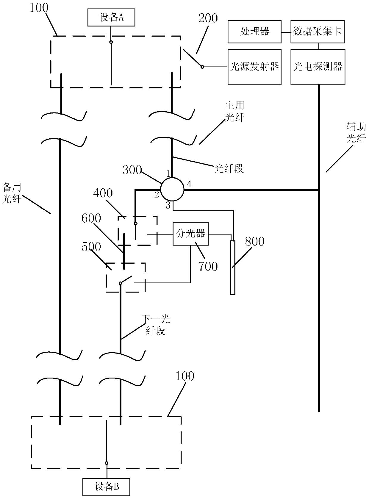
The invention provides an electric power communication laser scanning device. A main optical fiber is connected with a light source emitter and is divided into a plurality of optical fiber sections; for each optical fiber section, the second end, far away from the light source emitter, of the optical fiber section is connected with the first end of the circulator; the second end of the circulatoris respectively connected with the first end of the middle-section optical fiber and the input end of the optical splitter through a second change-over switch; the input end of the next optical fibersection is respectively connected with the second end of the middle section optical fiber and the first output end of the optical splitter through a third change-over switch; the second output end ofthe optical splitter is connected with the input end of the fiber Bragg grating; the reflection output end of each fiber Bragg grating is connected with the third end of the circulator, the fourth endof the circulator is connected with the auxiliary optical fiber, the photoelectric detector is connected with the auxiliary optical fiber, the wavelengths of optical signals capable of being reflected back by the fiber Bragg gratings are different, and the pulse intensities of the optical signals with different wavelengths in the light source signals provided by the light source emitter are different. The fault detection efficiency of the optical fiber section can be improved.

Description

technical field [0001] The invention belongs to the field of power communication network maintenance, and in particular relates to a power communication laser scanning device. Background technique [0002] At present, when detecting whether there is a fault in the power communication network, it is usually necessary for inspectors to go to the corresponding road section where the optical fiber is laid to detect the section of optical fiber. Obviously, the detection efficiency is low. Contents of the invention [0003] The invention provides a laser scanning device for electric power communication to solve the problem of low detection efficiency of faulty sections of optical fibers at present. [0004] According to the first aspect of the embodiments of the present invention, there is provided a power communication laser scanning device, which includes a main optical fiber, a backup optical fiber and an auxiliary optical fiber. Device A is respectively connected to the mai...

Claims


Application Information

Patent Timeline
Patent Type & Authority Patents(China)
IPC IPC(8): H04B10/079
CPCH04B10/0791H04B10/0795
Inventor 任永辉侯海波刘淼李震杨浩刘维特王吉朋张猛宋春蕾丛伟波孙丛李雪
Owner 任永辉
Learn More