Paper current collector, method for manufacturing same, and electrochemical device comprising paper current collector
A current collector and paper-based technology, applied in electrochemical generators, final product manufacturing, electrode carriers/collectors, etc., can solve difficult problems and achieve excellent mechanical flexibility, high energy density, and light weight
- Summary
- Abstract
- Description
- Claims
- Application Information
AI Technical Summary
Problems solved by technology
Method used
Image
Examples
preparation example 1
[0063] A suspension having a cellulose concentration of 0.5% obtained by adding cellulose fibers to water was stirred by using a stirrer for 20 minutes, and the suspension was passed through a nozzle 20 having a diameter of 50-200 μm under a pressure of 20000 psi using a homogenizer times to prepare a dispersion in which nanocellulose fibers with a diameter of 10-100 nm are dispersed.
Embodiment 1
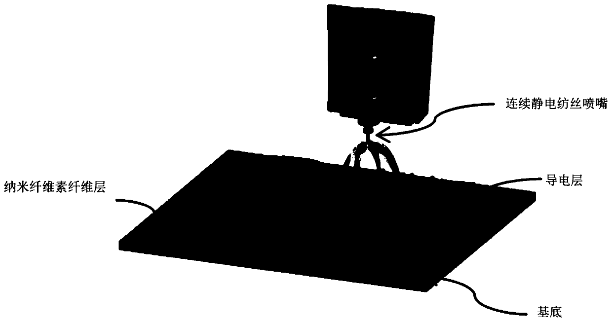
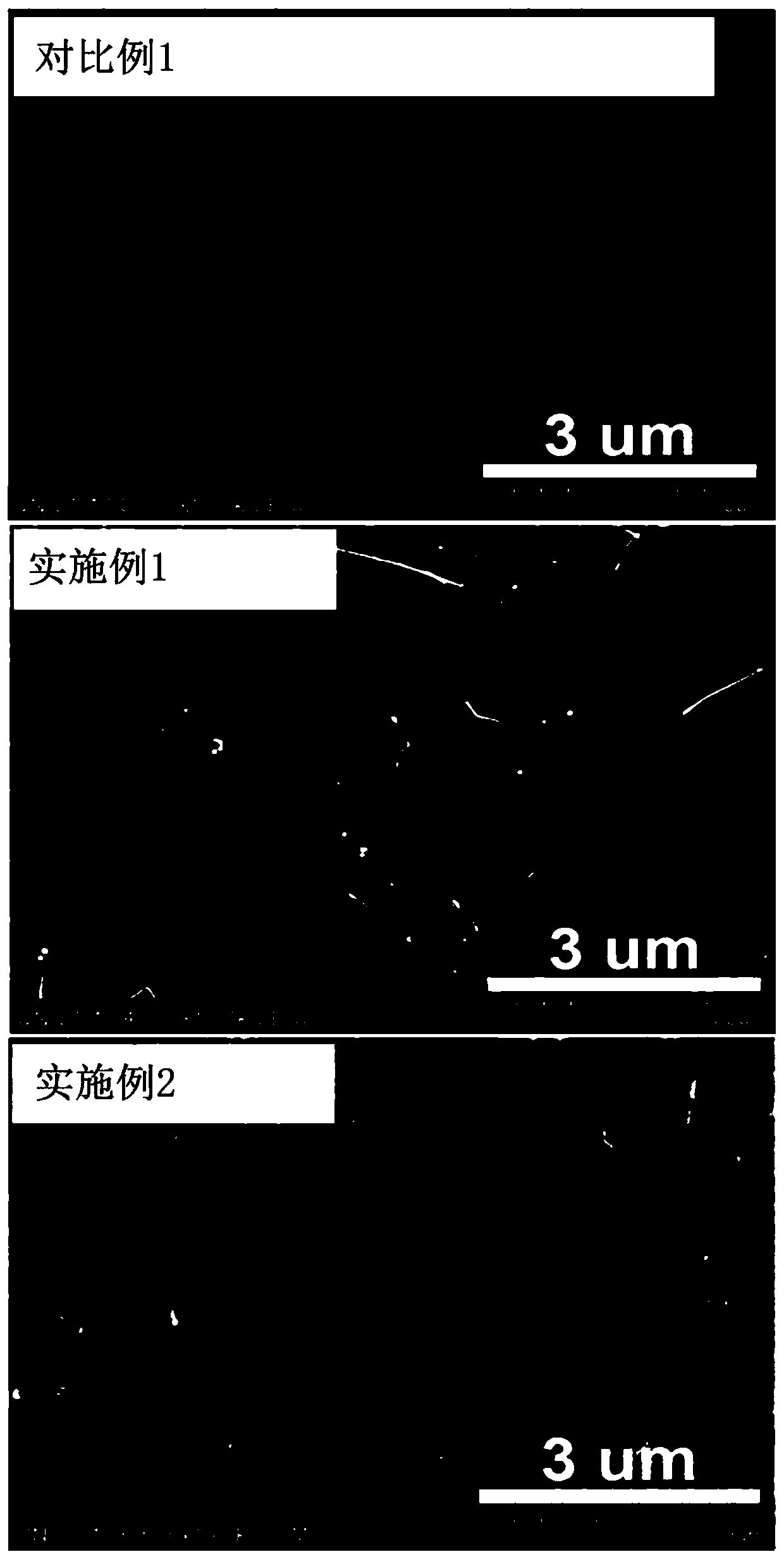
[0065] Nanocellulose paper was produced by placing the dispersion prepared in Preparation Example 1 at a continuous electrospinning nozzle of an electrospinning device for electrospinning. Here, the input voltage is controlled at 20±1kV, and the spinning speed is 20ml / hr per unit area (1cm 2 ) spinning 1 ml of spinning solution. Then, the isopropanol solution in which 1 wt% Ag nanowires were dispersed was placed at the continuous electrospinning nozzle, and electrospinning was performed on the fabricated nanocellulose paper to fabricate a paper current collector. Here, the input voltage is controlled at 15±1kV, and the spinning speed per unit area (1cm 2 ) spinning 0.5ml of spinning solution, and based on 100 parts by weight of nanocellulose paper, the content of the Ag nanowire layer included in the paper current collector is 10±5 parts by weight.
Embodiment 2
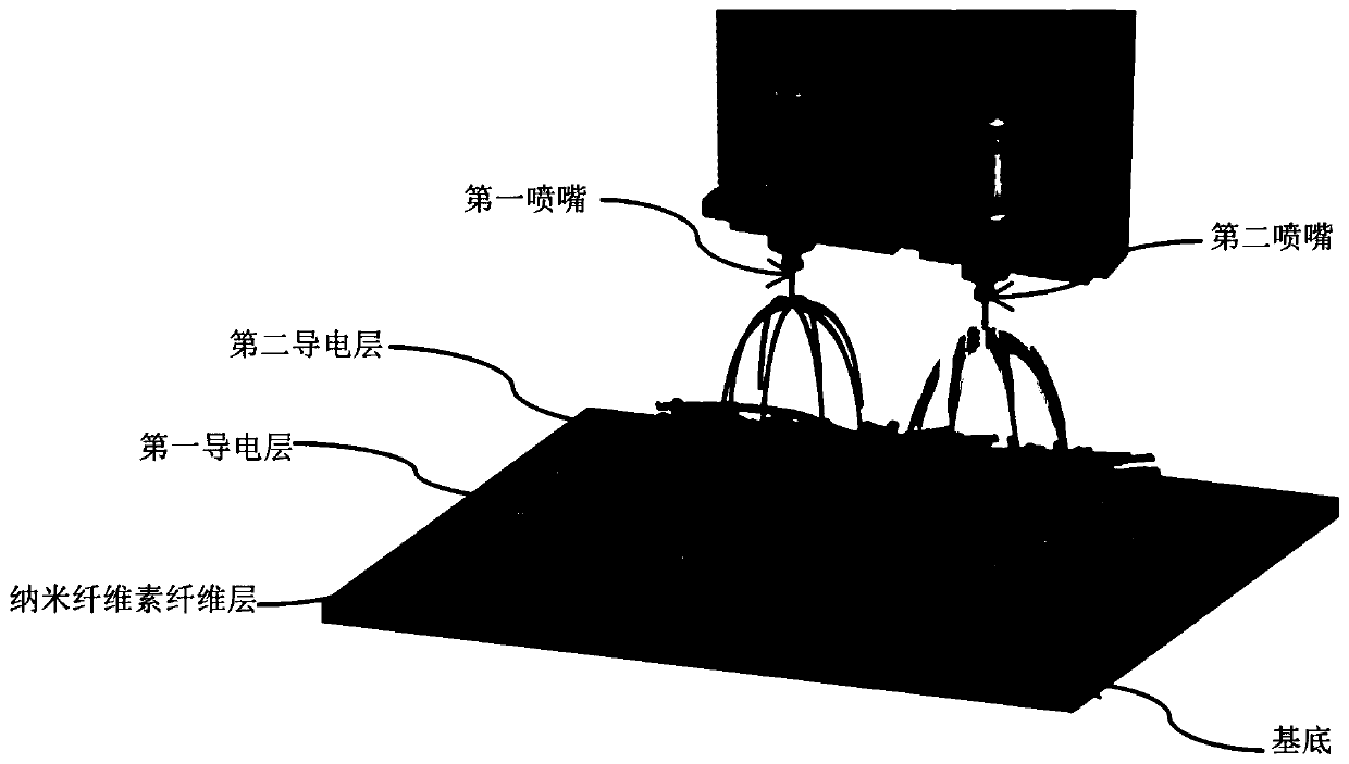
[0067] Using the dispersion liquid prepared in Preparation Example 1, nanocellulose paper was produced by the same method as in Example 1. Then, the isopropanol solution dispersed with 1 wt% Ag nanowires was injected into the first nozzle of the dual electrospinning device, and the aqueous solution dispersed with 0.01 wt% carbon nanotubes was injected into the second nozzle, and the Double electrospinning was performed on prefabricated nanocellulose paper to manufacture a paper current collector in which a first conductive layer including a first conductive material and a second conductive layer including a second conductive material were sequentially stacked. Here, the input voltages of the first nozzle and the second nozzle are controlled at 15±1kV and 18±1kV respectively, and the spinning speeds are 20±1ml / hr and 10±1ml / hr, and each unit area (1cm 2) The spinning amount is controlled at 0.5ml. In addition, based on 100 parts by weight of nanocellulose paper, the respective...
PUM
| Property | Measurement | Unit |
|---|---|---|
| diameter | aaaaa | aaaaa |
| diameter | aaaaa | aaaaa |
| diameter | aaaaa | aaaaa |
Abstract
Description
Claims
Application Information
 - R&D
- Intellectual Property
- Life Sciences
- Materials
- Tech Scout
- Unparalleled Data Quality
- Higher Quality Content
- 60% Fewer Hallucinations
Browse by: Latest US Patents, China's latest patents, Technical Efficacy Thesaurus, Application Domain, Technology Topic, Popular Technical Reports.
© 2025 PatSnap. All rights reserved.Legal|Privacy policy|Modern Slavery Act Transparency Statement|Sitemap|About US| Contact US: help@patsnap.com


