

Coil terminal structure
A coil and structure technology, applied in the direction of transformer/inductor coil/winding/connection, transformer/inductor parts, electrical components, etc., can solve problems such as difficult and time-consuming aluminum bonding
- Summary
- Abstract
- Description
- Claims
- Application Information
AI Technical Summary
Problems solved by technology
Method used
Image

Examples
no. 1 Embodiment approach
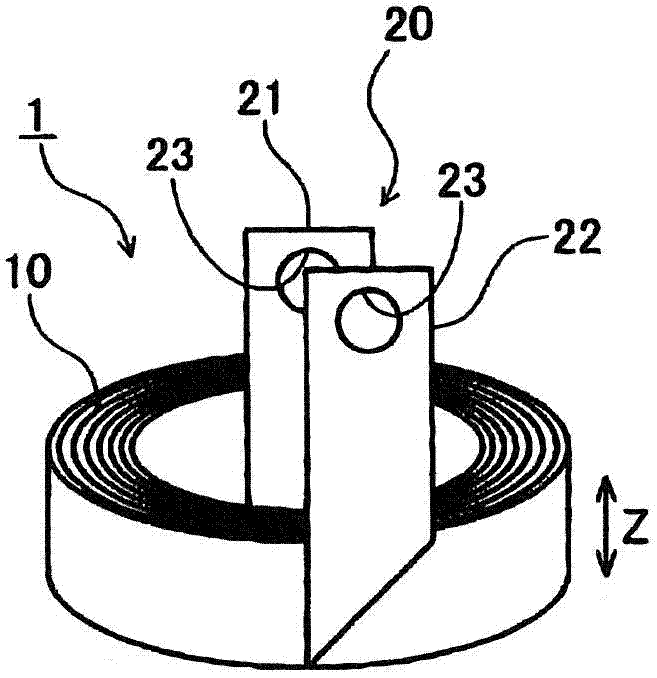
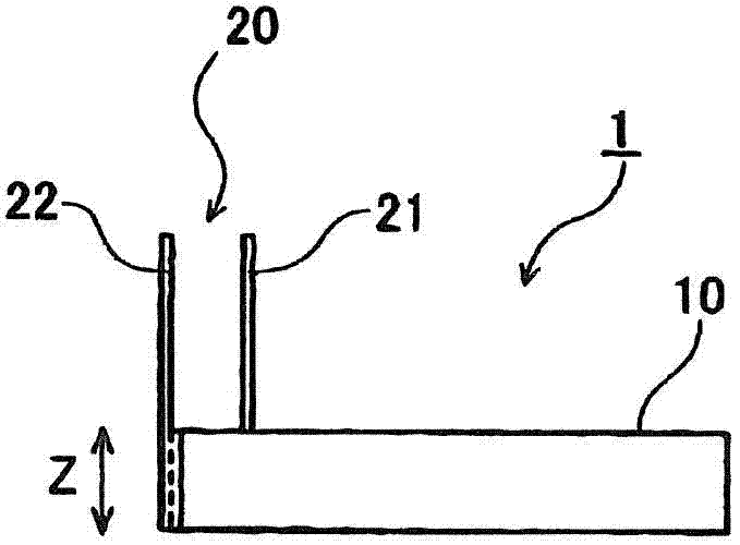
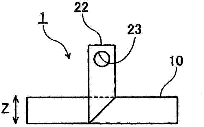
[0055] The coil terminal structure 1 of the first embodiment is used for components including coils such as choke coils and transformers. The coil terminals are constructed as 1 Figure 1 ~ Figure 3 As shown, it includes: a coil portion 10 formed by winding a thin metal plate; and a terminal portion 20 drawn out in the axial direction (Z direction) of the coil portion 10 by bending the end portion of the coil portion 10 .
[0056] In order to allow current to flow through the coil unit 10 , a terminal unit 20 for connecting to another external circuit is required. Therefore, by bending the inner peripheral end portion and the outer peripheral end portion of the coil portion 10, the inner terminal portion 21 and the outer terminal portion 22 pulled out in the axial direction (Z direction) of the coil portion 10 serve as terminal portions. 20 formed. Here, the inner terminal portion 21 and the outer terminal portion 22 are pulled out to the same side (upper side) in the axial...
no. 2 Embodiment approach
[0062] The coil terminal structure 200 of the second embodiment is as Figure 5 ~ Figure 7 As shown, it includes: a coil part 210 formed by winding a thin metal plate; .
[0063] The terminal portion 220 of the terminal structure 200 according to the second embodiment is bent such that the tip thereof faces the radial direction (R direction) of the coil portion 210 . Specifically, the coil is bent such that the inner terminal portion 221 formed at the inner peripheral end portion of the coil portion 210 faces radially inward and the outer terminal portion 222 formed at the outer peripheral end portion of the coil portion 210 faces radially outward. The inner peripheral end and the outer peripheral end of the portion 210. Thus, the inner terminal portion 221 has a vertical portion 221 a extending in the axial direction (Z direction) and a horizontal portion 221 b extending in the horizontal direction (radial inner side), and the outer terminal portion 222 has a vertical porti...
no. 3 Embodiment approach
[0067] The coil terminal structure 300 of the third embodiment is as Figure 8 and Figure 9 As shown, it includes: a coil portion 310 formed by winding a metal thin plate; and a terminal portion 320 drawn out in the axial direction (Z direction) of the coil portion 310 by bending the end portion of the coil portion 310 .
[0068] Such as Figure 8 As shown in (a) and (b), the portion S where the end portion of the coil portion 310 is bent in the axial direction (Z direction) is folded back at a predetermined position in the axial direction (Z direction), whereby the terminal portion 320 becomes double structure. In this third embodiment, the inner terminal portion 321 formed at the inner peripheral end portion of the coil portion 310 and the outer terminal portion 322 formed at the outer peripheral end portion of the coil portion 310 each have a double structure. The number of turns of the terminal portion 320 may be appropriately selected in consideration of the strength ...
PUM
 Abstract
Description
Claims
Application Information