Self-excited push-pull conversion circuit

A conversion circuit, self-excited technology, applied in the direction of output power conversion devices, electrical components, regulating electrical variables, etc., can solve the problems of reducing power conversion efficiency, increasing line normal power loss, etc., to ensure electrical characteristics and power supply. Conversion efficiency, shortening transition time, and increasing power loss

Active Publication Date: 2018-09-25
MINMAXTECH
View PDF7 Cites 0 Cited by
  • Summary
  • Abstract
  • Description
  • Claims
  • Application Information

AI Technical Summary

Problems solved by technology

[0005] In order to shorten the transition time of the transistor, the existing practice can increase the start-up power. It is necessary to design a higher start-up power to allow the transistor to establish a correct operating point, so that it can quickly enter the switching region (that is: saturation region or cut-off region) instead of entering the active region, but the differences in the electrical characteristics of the existing two transistors and passive components, the transistor operating region falls at the intersection of the active region and the saturation region or the cut-off region, so there will be differences in electrical operating characteristics However, to improve this difference will enhance the driving ability of the transistor so that it does not fall in the fuzzy zone, but as the startup power increases, it also increases the normal power loss of the line and relatively reduces the power conversion efficiency

Method used


Image

  • Self-excited push-pull conversion circuit
  • Self-excited push-pull conversion circuit
  • Self-excited push-pull conversion circuit

Examples


Embodiment Construction

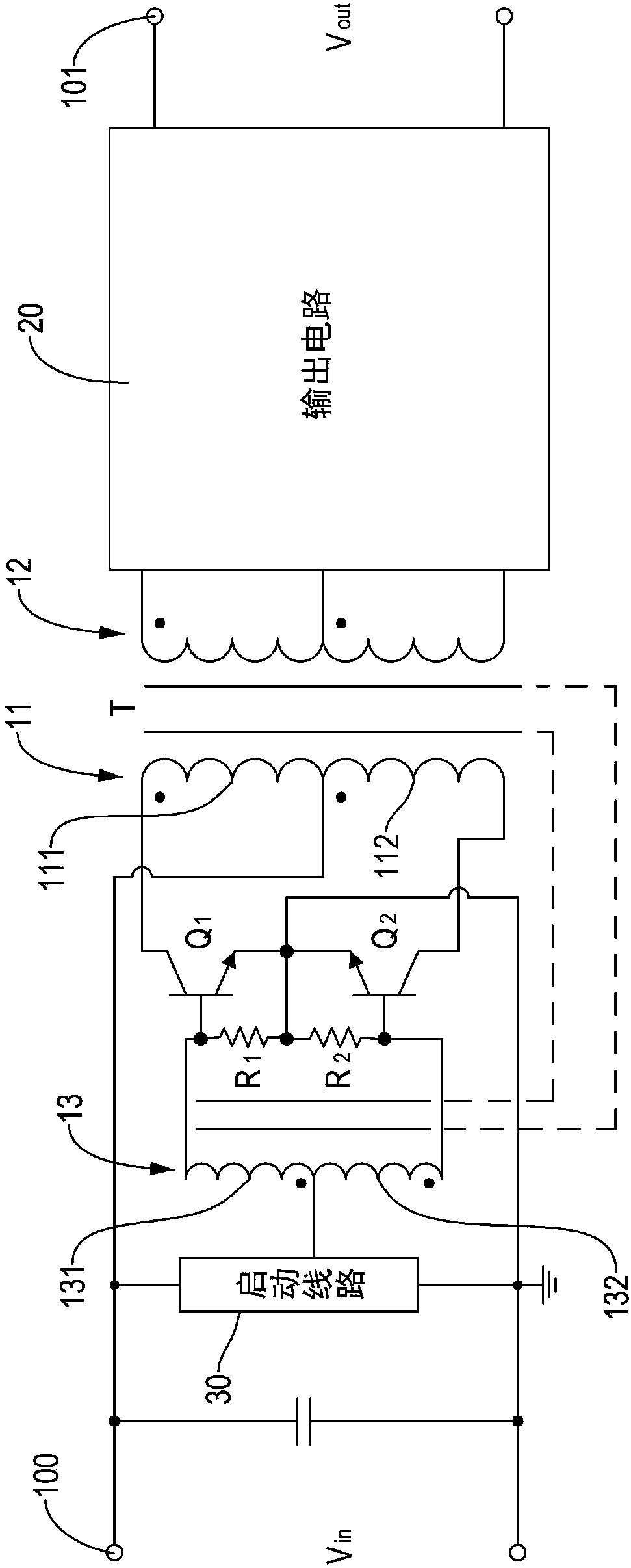
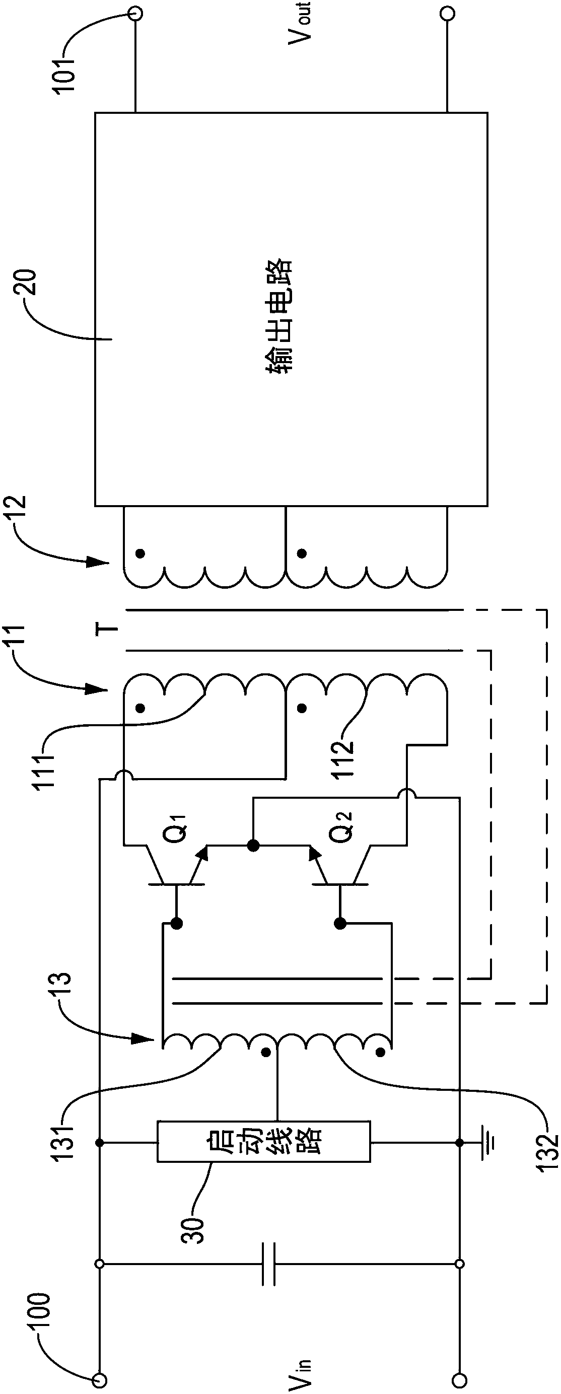
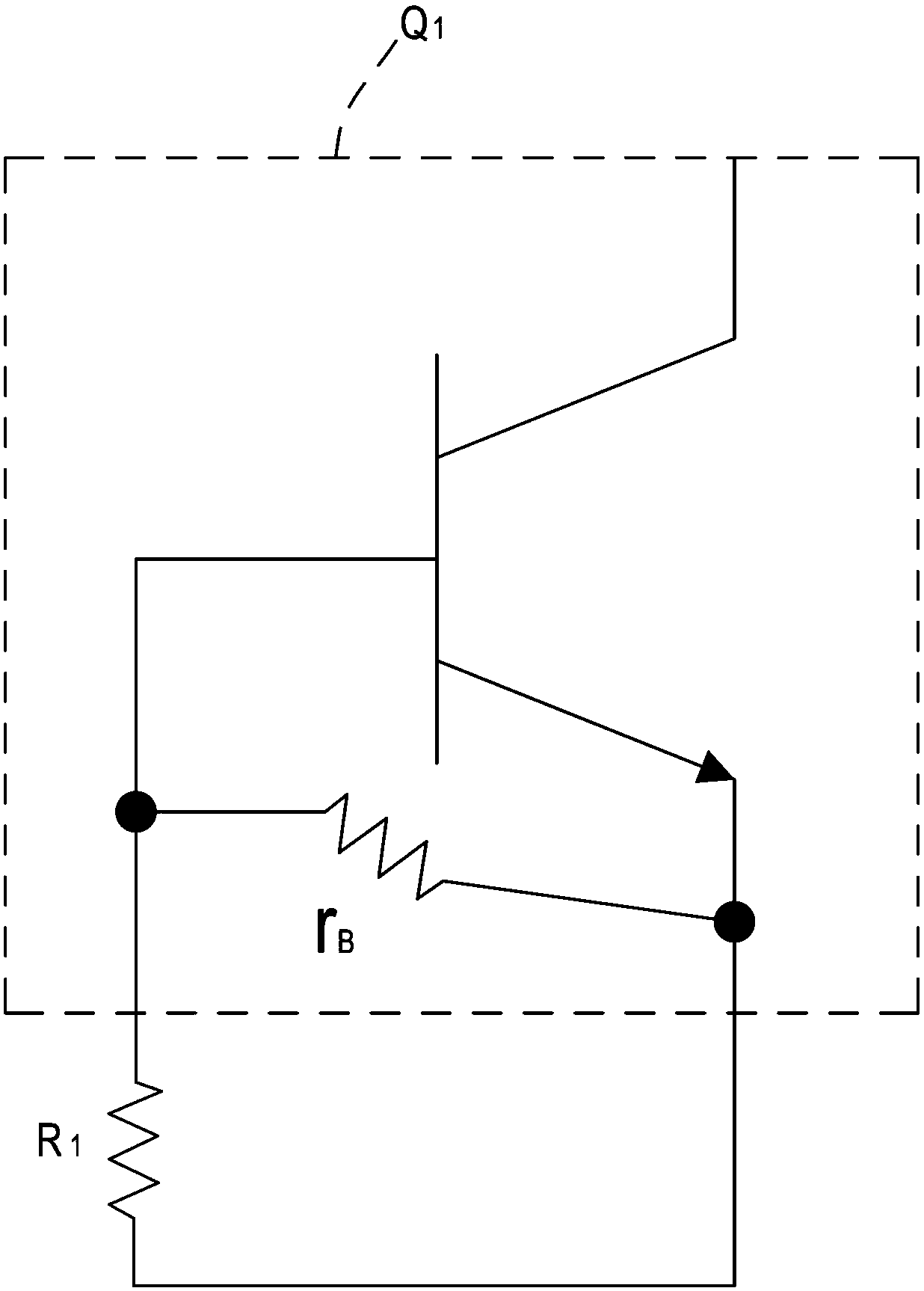
[0037] Please refer to figure 1 and figure 2 , the self-excited push-pull conversion circuit of the present invention comprises a push-pull circuit unit, a first resistor R 1 with a second resistor R 2 . The push-pull circuit unit may be a typical self-excited push-pull circuit, such as a typical Royer circuit or a typical Jensen circuit. In the embodiment of the present invention, the push-pull circuit unit includes an input terminal 100, a first transistor Q 1 , a second transistor Q 2 with a transformer T.

[0038] The first transistor Q 1 with the second transistor Q 2 It can be a three-terminal control element, each including a power supply terminal, a ground terminal and a control terminal. In the embodiment of the present invention, the first transistor Q 1 with the second transistor Q 1 may be bipolar junction transistors (Bipolar Junction Transistor, BJT), but not limited thereto, the power supply terminal is a collector terminal (Collector, C), and the grou...


PUM


Abstract

A self-excited push-pull conversion circuit comprises a push-pull circuit unit, a first resistor and a second resistor, wherein the push-pull circuit unit comprises a first transistor and a second transistor. There are input impedances between the control ends of the first and second transistors and a ground end. The first resistor is connected in parallel to the input impedance of the first transistor, and the second resistor is connected in parallel to the input impedance of the second transistor. Through the parallel circuit architecture mentioned above, the equivalent input total impedanceof the first transistor and the second transistor can be reduced by the Ohm's law, and thus the circuit architecture can be established at a clear operating point, so that the first transistor and the second transistor can quickly shift between a saturation region and a cutoff region.

Description

technical field [0001] The invention relates to a direct current to direct current conversion circuit, in particular to an improved self-excited push-pull conversion circuit. Background technique [0002] Existing self-oscillating push-pull converter circuits (Self-Oscillating Push-Pull Converter) include, for example, a typical Royer circuit or a typical Jensen circuit, which mainly includes two transistors and a transformer. The two transistors may be bipolar junction transistors (Bipolar Junction Transistor, BJT), the bases of the two transistors are respectively electrically connected to an input terminal through the two auxiliary windings in the transformer, and the collectors of the two transistors are respectively Connect the transformer primary side winding. It should be noted that even though the two transistors have the same type, the electrical characteristics of the two transistors are still not completely the same; therefore, the differences in the transistors ...

Claims


Application Information

Patent Timeline
Patent Type & Authority Applications(China)
IPC IPC(8): H02M3/337
CPCH02M3/337
Inventor 陈政鸿李聪贤黄昱豪高志明
Owner MINMAXTECH
Why Eureka
Try Eureka