Axial Positioning Drilling Device for Shaft Workpieces

A technology for axial positioning and drilling devices, applied in positioning devices, boring/drilling, drilling/drilling equipment, etc., can solve the problem that shaft parts cannot effectively achieve shaft surface positioning and it is difficult to effectively ensure cutting Punching accuracy and efficiency, and the inability to effectively realize cutting and punching operations, etc., to achieve the effects of good practicability, stable and reliable use, and reasonable structure settings

Active Publication Date: 2020-09-11
靖江市鑫晟汽车零部件制造有限公司
View PDF10 Cites 0 Cited by
  • Summary
  • Abstract
  • Description
  • Claims
  • Application Information

AI Technical Summary

Problems solved by technology

[0002] Shaft parts are typical parts often encountered in hardware accessories. They are mainly used to support transmission parts, transmit torque and bear loads. In order to meet the needs of other parts, lubrication, manufacturing and testing, it is necessary to punch holes on the shaft. Operations, such as screw holes, grease holes and center holes, etc., in the prior art, there are many types of cutting and drilling devices, but most of them cannot effectively realize the cutting and drilling operations in the axial direction, mainly because the shaft parts cannot be effectively The positioning of the shaft surface is realized, and the smoothness of the shaft surface is easily damaged during positioning, so it is difficult to effectively ensure the accuracy and efficiency of cutting and drilling, so the applicability and practicability are limited

Method used


Image

  • Axial Positioning Drilling Device for Shaft Workpieces
  • Axial Positioning Drilling Device for Shaft Workpieces

Examples


Embodiment 1)

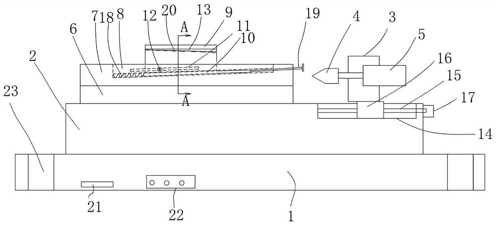
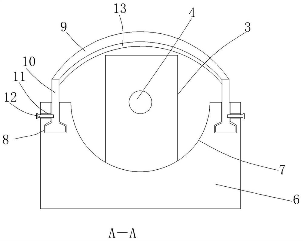
[0017] figure 1 and figure 2 A specific embodiment of the invention is shown in which figure 1 It is a structural schematic diagram of the present invention; figure 2 for figure 1 A-A sectional view in .

[0018] See figure 1 and figure 2 , an axial positioning drilling device for shaft workpieces, comprising a base 1, a processing platform 2 arranged on the base 1, a drilling seat 3 is provided on the top surface side of the processing platform 2, A drilling tool 4 and a driving motor 5 connected with the drilling tool are horizontally arranged on the drilling seat, a positioning seat 6 is arranged on the processing platform, and a positioning seat 6 is arranged on the top surface of the positioning seat. The U-shaped workpiece placement groove 7 is provided with two dovetail-shaped chutes 8 on the positioning seat, and the two dovetail-shaped chutes are respectively arranged on both sides of the U-shaped workpiece placement groove and the dovetail-shaped chutes are ...


PUM


Abstract

The invention discloses an axial positioning drilling device for a shaft type workpiece. The axial positioning drilling device comprises a base and a processing platform arranged on the base; a drilling seat is arranged on the side portion of the top face of the processing platform, a drilling tool and a driving motor connected to the drilling tool are arranged on the drilling seat in the horizontal direction, a positioning seat is arranged on the processing platform, a U-shaped workpiece placing groove is arranged in the top surface of the positioning seat, two dovetail sliding grooves are formed in the positioning seat, the two dovetail sliding grooves are arranged on the two sides of the U-shaped workpiece placing groove and are arranged in an inclined manner, and the inclined top endsof the dovetail sliding grooves are close to the drilling seat; and an n-shaped positioning pressure block is arranged on the positioning seat, inverted T-shaped sliders are fixed to the two ends of the n-shaped positioning pressure block, a locking slot hole is formed in the side portion of the positioning seat, and locking screws are arranged on the inverted T-shaped sliders. The axial positioning drilling device is reasonable in structure arrangement, the drilling precision can be ensured, the drilling efficiency can be greatly improved, the using stability and reliability are achieved, theapplicability is strong, and the practicability is good.

Description

technical field [0001] The invention belongs to the technical field of shaft workpiece processing equipment, and in particular relates to an axial positioning drilling device for shaft workpieces. Background technique [0002] Shaft parts are typical parts often encountered in hardware accessories. They are mainly used to support transmission parts, transmit torque and bear loads. In order to meet the needs of other parts, lubrication, manufacturing and testing, it is necessary to punch holes on the shaft. Operations, such as screw holes, grease holes and center holes, etc., in the prior art, there are many types of cutting and drilling devices, but most of them cannot effectively realize the cutting and drilling operations in the axial direction, mainly because the shaft parts cannot be effectively The positioning of the shaft surface is realized, and the smoothness of the shaft surface is easily damaged during positioning, so it is difficult to effectively ensure the accur...

Claims


Application Information

Patent Timeline
Patent Type & Authority Patents(China)
IPC IPC(8): B23B41/00B23Q3/06
CPCB23B41/00B23Q3/062
Inventor 刘安胜
Owner 靖江市鑫晟汽车零部件制造有限公司
Why Eureka
Try Eureka