Front-rear rotary type flapping wing paddle

A rotary and propeller technology, applied in the field of propellers, can solve the problems of low efficiency of propellers, achieve good fluid power, high-efficiency lift or thrust, and increase the effect of pressure difference between the upper and lower sides

Inactive Publication Date: 2019-07-26
姚登元
View PDF0 Cites 0 Cited by
  • Summary
  • Abstract
  • Description
  • Claims
  • Application Information

AI Technical Summary

Problems solved by technology

[0004] The main purpose of the present invention is to provide a forward and backward rotating flapping propeller, to solve the problem of low efficiency of the propeller in the prior art

Method used


Image

  • Front-rear rotary type flapping wing paddle
  • Front-rear rotary type flapping wing paddle
  • Front-rear rotary type flapping wing paddle

Examples


Embodiment Construction

[0019] It should be noted that, in the case of no conflict, the embodiments in the present application and the features in the embodiments can be combined with each other. The present invention will be described in detail below with reference to the accompanying drawings and examples.

[0020] It should be noted that, unless otherwise specified, all technical and scientific terms used in this application have the same meaning as commonly understood by those of ordinary skill in the art to which this application belongs.

[0021] In the present invention, unless stated to the contrary, the used orientation words such as "upper, lower, top, and bottom" are usually for the direction shown in the drawings, or for the direction itself in vertical, vertical or In terms of the direction of gravity; similarly, for ease of understanding and description, "inside and outside" are relative to the inside and outside of the outline of each component itself, but the above orientation words a...


PUM


Abstract

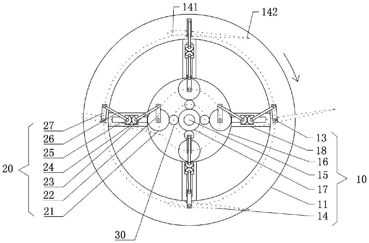
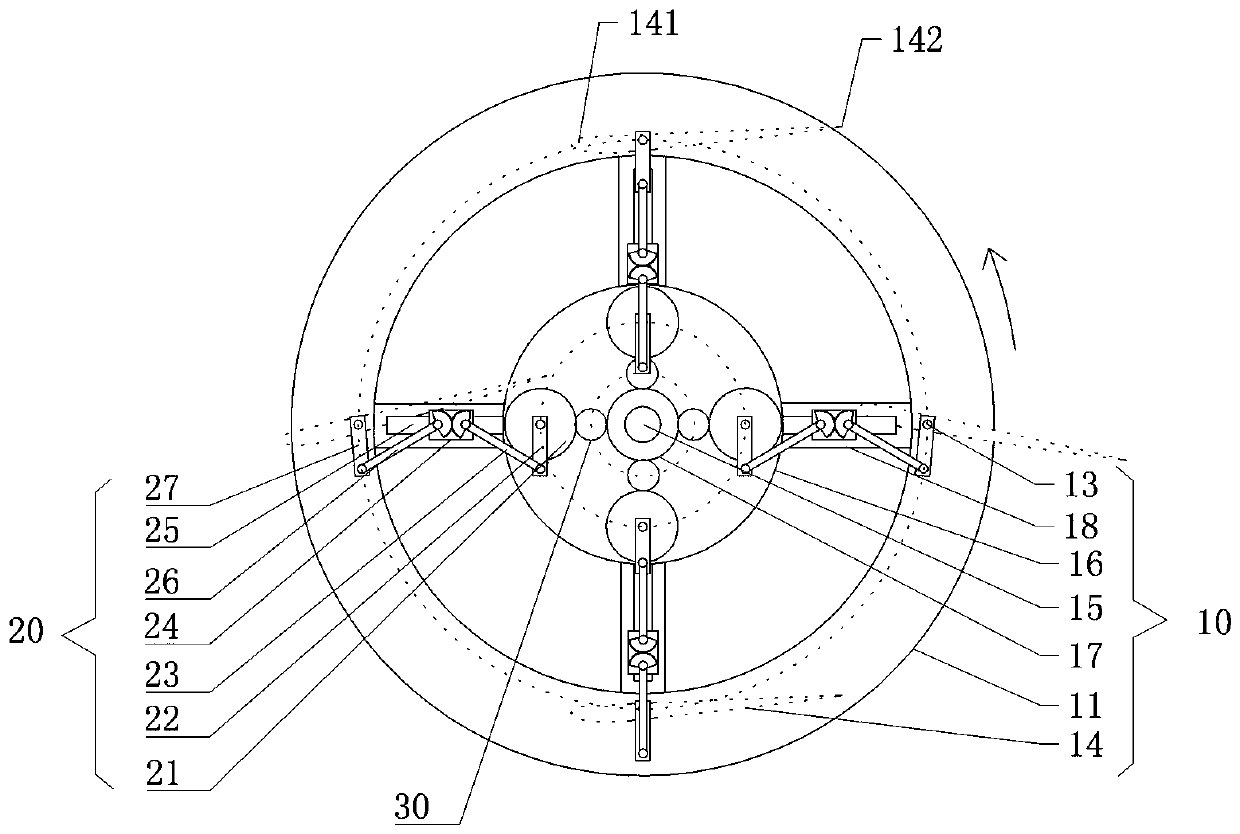
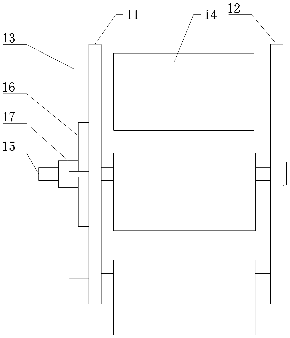
The invention discloses a front-rear rotary type flapping wing paddle. The front-rear rotary type flapping wing paddle comprises a paddle frame and at least two paddle blades, the paddle blades are rotatably connected to the paddle frame through blade shafts, a center shaft of the paddle frame is connected with an output shaft of a power device in a transmission mode, the paddle blades are drivenby the power device to rotate along with the paddle frame, one ends of the blade shafts extend outside the paddle frame and are hinged to an output end of a transmission assembly, an input end of thetransmission assembly is connected with the output end of the power device in a transmission mode, and the transmission assembly is used for keeping the front edges of the paddle blades to always point forward. The problem that the efficiency of rotor wing paddles in the prior art is low is effectively solved.

Description

technical field [0001] The invention belongs to the technical field of propellers, and more specifically, the present invention relates to a forward and backward rotating flapping propeller. Background technique [0002] Nowadays, ships and aircrafts of various sizes mostly adopt the mode of propeller rotation propulsion to obtain propulsion power. The efficiency of the propeller is not high, and part of the energy is wasted on the resistance of the propeller rotation. When the speed is extremely high, its propulsion efficiency will decrease instead, and the hydrodynamic noise of the propeller is very loud. Many fields have to reduce the propeller Speed ​​and propulsion capacity to reduce the noise generated during propulsion. Therefore, the current research on bionic propulsion technology has received extensive attention. The main problem is that it is difficult to generate sufficient propulsion. The main reason is that the rigid structure and movement mode are difficult t...

Claims


Application Information

Patent Timeline
Patent Type & Authority Applications(China)
IPC IPC(8): B64C33/02B63H1/36
CPCB63H1/36B64C33/02
Inventor 姚登元
Owner 姚登元
Why Eureka
Try Eureka