Catenary flexible lifting appliance

A flexible and spreader technology, applied in the direction of load hanging components, transportation and packaging, etc., can solve the problems of time-consuming and laborious, poor adaptability and occupied area, and achieve improved adaptability, smaller occupied area and simple structure Effect

Pending Publication Date: 2019-07-26
FAW CAR CO LTD
View PDF0 Cites 0 Cited by
  • Summary
  • Abstract
  • Description
  • Claims
  • Application Information

AI Technical Summary

Problems solved by technology

[0003] The invention provides a catenary flexible suspension structure, which can effectively solve the problems of occupied area, time-consuming and labor-intensive problems caused by the poor adaptability of the catenary suspension in the prior art

Method used


Image

  • Catenary flexible lifting appliance
  • Catenary flexible lifting appliance
  • Catenary flexible lifting appliance

Examples


Embodiment 1

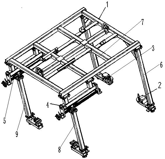
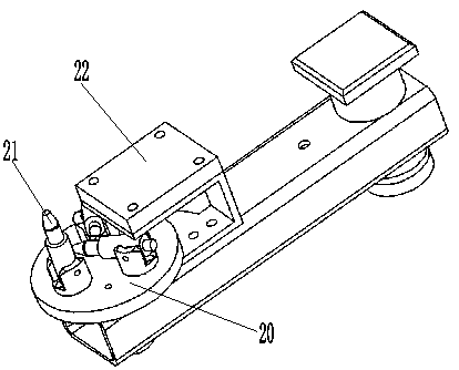
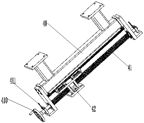
[0026] When hoisting the M1 platform body, first adjust the spiral turntable 20 on the first support leg 6 and the second support leg 7, erect the M1 platform positioning pin 21 on the spiral turntable 20, and put the rest of the vehicle body positioning pins 21 down, Another positioning pin is used to fix the spiral turntable 20 on the base 22, adjust the first adjustment mechanism 4 and the second adjustment mechanism 5 of the third leg 8 and the fourth leg 9, and adjust the third leg 8 and the fourth leg. Outrigger 9 is adjusted to correct position, and vehicle body is hoisted on the spreader.

Embodiment 2

[0028] When hoisting the M2 platform body, first adjust the spiral turntable 20 on the first support leg 6 and the second support leg 7, erect the M2 platform positioning pin 21 on the spiral turntable 20, put down the rest of the vehicle body positioning pins 21, Another positioning pin is used to fix the spiral turntable 20 on the base 22, adjust the first adjustment mechanism 4 and the second adjustment mechanism 5 of the third leg 8 and the fourth leg 9, and adjust the third leg 8 and the fourth leg. Outrigger 9 is adjusted to correct position, and vehicle body is hoisted on the spreader.

Embodiment 3

[0030] When hoisting the M3 platform body, first adjust the spiral turntable 20 on the first support leg 6 and the second support leg 7, erect the M3 platform alignment pin 21 on the spiral turntable 20, and put down the rest of the body alignment pins 21, Another positioning pin is used to fix the spiral turntable 20 on the base 22, adjust the first adjustment mechanism 4 and the second adjustment mechanism 5 of the third leg 8 and the fourth leg 9, and adjust the third leg 8 and the fourth leg. Outrigger 9 is adjusted to correct position, and vehicle body is hoisted on the spreader.


PUM


Abstract

The invention discloses a catenary flexible lifting appliance. The catenary flexible lifting appliance comprises a framework structure, a first rotary positioning mechanism, a second rotary positioning mechanism, a first adjusting mechanism, a second adjusting mechanism, a first supporting leg, a second supporting leg, a third supporting leg and a fourth supporting leg, wherein the front end of the frame structure is connected with the first rotary positioning mechanism and the second rotary positioning mechanism through the first support leg and the second support leg, the rear end of the frame structure is connected with the third supporting leg and the fourth supporting leg through the first adjusting mechanism and the second adjusting mechanism, and a spiral rotating disc is adopted, so that the lifting appliance can be used for meeting the positioning of a plurality of types of automobiles; the position of the third supporting leg and the position of the fourth supporting leg canbe adjusted by using the first adjusting mechanism and the second adjusting mechanism, so that the hoisting requirements of different vehicle lengths can be met, the stability is guaranteed, and the adaptability is improved; and positioning holes in the bottoms of vehicle bodies of different types are different, so that the first rotary positioning mechanism and the second rotary positioning mechanism are additionally arranged on the lifting appliance so as to meet the positioning requirements of the multiple vehicle types.

Description

technical field [0001] The invention relates to the technical field of automobile manufacturing, in particular to a catenary flexible hanger. Background technique [0002] The automobile industry is one of the pillar industries of my country's national economy, and the R&D and trial production stage is one of the pillar industries of the automobile industry. In the process of R&D and trial production of new automobile products, the existing spreaders cannot fully meet the needs of models with different car bodies and different wheelbases. If the trial production is carried out on different spreaders, it will result in the need for multiple spreaders, and the floor area will change. Large, supporting facilities increase, the process is time-consuming and laborious, and the cost increases. Contents of the invention [0003] The invention provides a catenary flexible suspension structure, which can effectively solve the problems of occupying an area, time-consuming and labor...

Claims


Application Information

Patent Timeline
Patent Type & Authority Applications(China)
IPC IPC(8): B66C1/10
CPCB66C1/10
Inventor 赵洪伟王鹏李阳
Owner FAW CAR CO LTD
Why Eureka
Try Eureka