Water absorption floor tile

A technology of floor tiles and water suction pipes, used in roads, buildings, side ditch/curbstone, etc., can solve the problems of pedestrian discomfort, poor buffering effect, pedestrian slipping and falling, etc., to improve the water absorption effect, increase friction, improve The effect of comfort

Active Publication Date: 2019-07-26
宜都市徽仁环保科技有限公司
View PDF4 Cites 12 Cited by
  • Summary
  • Abstract
  • Description
  • Claims
  • Application Information

AI Technical Summary

Problems solved by technology

Since most of the floor tiles are fired from clay, they have poor water absorption. Once water accumulates on the surface of the floor tiles, it is easy for pedestrians to slip and fall, especially for the elderly or disabled people with inconvenient legs and feet; The surface is mostly hard, and the cushioning effect is extremely poor. Pedestrians step on the hard floor tiles for a long time, which is likely to cause numbness on the soles of the feet and bring discomfort to pedestrians.

Method used


Image

  • Water absorption floor tile
  • Water absorption floor tile
  • Water absorption floor tile

Examples


Embodiment 1

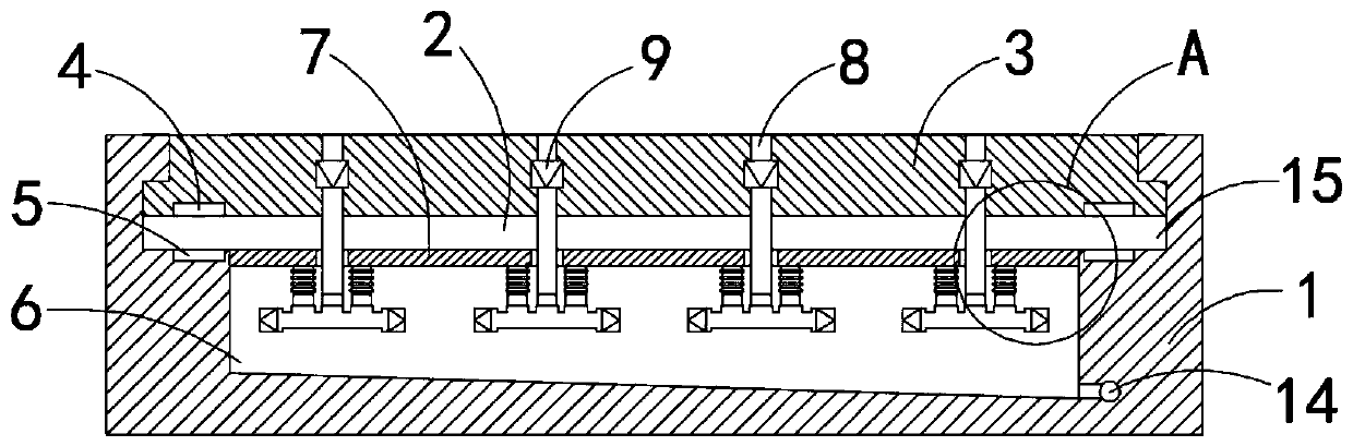
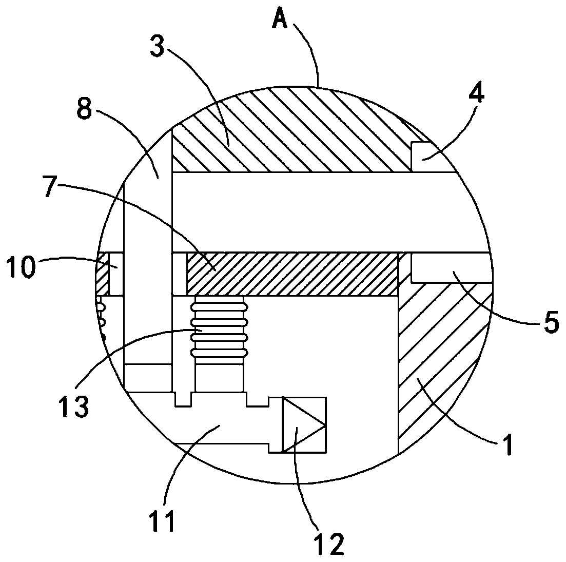
[0022] Such as Figure 1-4 As shown, a water-absorbing floor tile includes a brick body 1, a chute 2 is provided at the upper end of the brick body 1, and a floating plate 3 is slid inside the chute 2. Specifically, a limiting groove 15 is provided on the side wall of the chute 2 The edge of the floating plate 3 extends to the limit groove 15, the lower end of the floating plate 3 is embedded with the first permanent magnet ring 4, the bottom side wall of the chute 2 is embedded with the second permanent magnet ring 5, and the first permanent magnet ring 5 is embedded in the bottom side wall of the chute 2. The magnetic ring 4 and the second permanent magnetic ring 5 repel each other with the same polarity, the bottom of the chute 2 is provided with a water storage tank 6, the bottom side wall of the water storage tank 6 is inclined, and the bottom side wall of the water storage tank 6 is close to the drainage The channel 14 is provided to facilitate the collection of the wate...

Embodiment 2

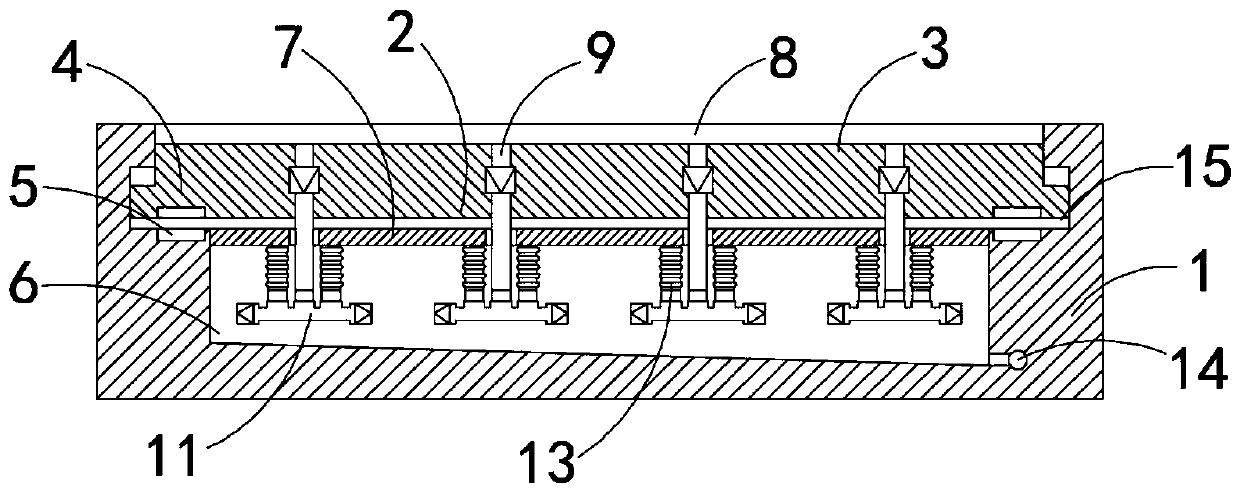
[0027] Such as Figure 5-6 As shown, the difference between this embodiment and Embodiment 1 is that the upper end of the floating plate 3 is provided with a groove 16 that matches the water suction pipe 8, and the bottom of the groove 16 communicates with the input end of the water suction pipe 8, and The bottom of the groove 16 is arc-shaped.

[0028] In this embodiment, since the groove 16 is set in a hemispherical depression, it can play the role of collecting water flow, so that the water absorption effect is more obvious.


PUM


Abstract

The invention belongs to the technical field of construction, and particularly relates to a water absorption floor tile. The water absorption floor tile comprises a tile body; a sliding groove is formed in the upper end of the tile body, and a floating plate is slidably arranged in the sliding groove; a first permanent magnet ring is arranged at the lower end of the floating plate in an embedded mode, and a second permanent magnet ring is arranged on the bottom side wall of the sliding groove in an embedded mode; the first permanent magnet ring and the second permanent magnet ring achieve homopolar repulsion; a water storage tank is arranged at the bottom of the sliding groove, and a tank opening of the water storage tank is fixedly connected with a limiting plate; a plurality of water absorption pipes are fixedly connected to the floating plate in a penetrating mode; one-way entering valves are fixedly connected to the water absorption pipes; through holes matched with the water absorption pipes are formed in the limiting plate, and the lower ends of the water absorption pipes penetrate through the through holes and are fixedly connected with horizontally-arranged drainage pipes;one-way discharge valves are fixedly connected to the two ends of the drainage pipes correspondingly; and the side walls of the drainage pipes fixedly communicate with a plurality of elastic corrugated pipes, and the upper ends of the elastic corrugated pipes and the lower surface of the limiting plate are fixedly connected. The water absorption floor tile is good in water absorption effect, can achieve the high anti-slipping effect, and meanwhile is high in buffering property and good in comfort.

Description

technical field [0001] The invention belongs to the field of construction, in particular to a water-absorbing floor tile. Background technique [0002] Floor tiles are a common building material used to pave roads. Since most of the floor tiles are fired from clay, they have poor water absorption. Once water accumulates on the surface of the floor tiles, it is easy for pedestrians to slip and fall, especially for the elderly or disabled people with inconvenient legs and feet; Most of the surfaces are hard, and the cushioning effect is extremely poor. Pedestrians step on the hard floor tiles for a long time, which is likely to cause numbness on the soles of the feet and bring discomfort to pedestrians. [0003] For this reason, we propose a water-absorbing floor tile to solve the above problems. Contents of the invention [0004] The object of the present invention is to solve the above problems and provide a water-absorbing and non-slip cushioning floor tile with outstan...

Claims


Application Information

Patent Timeline
Patent Type & Authority Applications(China)
IPC IPC(8): E01C11/22E01C15/00
CPCE01C11/225E01C15/00
Inventor 苟洪斌
Owner 宜都市徽仁环保科技有限公司
Why Eureka
Try Eureka