Fluid trigger-based infinite loop well washing tool and use method thereof

An infinite circulation, fluid technology, applied in the direction of flushing wellbore, earthmoving, wellbore/well components, etc., can solve the problem of limiting the number of times the circulation valve is opened

Pending Publication Date: 2019-07-26
成都阿斯贝瑞科技有限公司
View PDF2 Cites 3 Cited by
  • Summary
  • Abstract
  • Description
  • Claims
  • Application Information

AI Technical Summary

Problems solved by technology

The fluid-activated circulation switch valve has a fast response speed and is less affected by the inclination angle of the well. By adjusting the displacement, the transposition piston produces different axial displacements under the action of the displacement, which solves the limitation of the opening times of the existing circulation valve and the need to repeat The problem of tripping and resetting the valve; the structure is compact, the installation position is flexible, and a variety of inclinometer methods can be used

Method used


Image

  • Fluid trigger-based infinite loop well washing tool and use method thereof
  • Fluid trigger-based infinite loop well washing tool and use method thereof
  • Fluid trigger-based infinite loop well washing tool and use method thereof

Examples


Embodiment 1

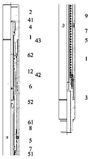
[0044] Such as Figure 1 to Figure 3 As shown, a fluid-inspired infinite circulation well cleaning tool includes a main barrel (1), an upper joint (2) connected to the main barrel (1) through threads, and a lower joint (2) connected to the main barrel (1) through threads. 3), fixed on the upper mandrel (4) of the upper joint (2), fixed on the lower mandrel (5) of the lower joint (3), installed on the piston (6) inside the main cylinder (1), installed on the lower The displacement spring (7) between the mandrel (5) and the piston assembly (5), the displacement element (8) and the limit element (9) fixed on the main cylinder (1), the upper mandrel ( 4) There are through holes (41), upper mandrel bypass holes (42) and pressure holes (43) on the upper side, and blind holes (51) and lower mandrel bypass holes (52) are opened on the lower mandrel , the piston (6) is provided with a transposition slot (61) and the piston bypass hole (62), the main cylinder (1) is provided with a wat...

Embodiment 2

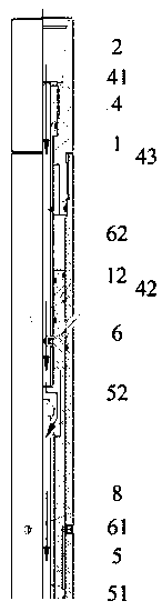
[0049] Such as Figure 4 to Figure 6 As shown, a fluid-inspired infinite circulation well cleaning tool includes a main barrel (1), an upper joint (2) connected to the main barrel (1) through threads, and a lower joint (2) connected to the main barrel (1) through threads. 3), fixed on the upper mandrel (4) of the upper joint (2), fixed on the lower mandrel (5) of the lower joint (3), installed on the piston (6) inside the main cylinder (1), installed on the lower The displacement spring (7) between the mandrel (5) and the piston assembly (5), the displacement element (8) and the limit element (9) fixed on the main cylinder (1), the upper mandrel ( 4) There are through holes (41), upper mandrel bypass holes (42) and pressure holes (43) on the upper side, and blind holes (51) and lower mandrel bypass holes (52) are opened on the lower mandrel , the piston (6) is a split piston consisting of an upper piston body (63) and a displacement piston body (64), and the piston bypass hol...

Embodiment 3

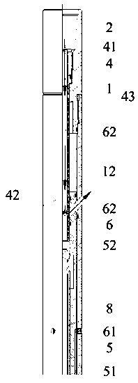
[0055] Such as Image 6 As shown, this embodiment is basically the same as Embodiment 2, the difference is that: the central axis of the piston bypass hole (62) and the central axis of the water hole (12) both intersect the axis of the main cylinder, and the piston bypass hole The angle range between the central axis of the through hole (62) and the central axis of the water hole (12) relative to the axis of the main cylinder is between 20° and 80°.

[0056] Further, the angle between the central axis of the piston bypass hole (62) and the central axis of the water hole (12) relative to the axis of the main barrel is 45°.


PUM

PropertyMeasurementUnit
Diameteraaaaaaaaaa

Abstract

The invention discloses a fluid trigger-based infinite loop well washing tool and a use method thereof. The fluid trigger-based infinite loop well washing tool includes a main cylinder, an upper jolt,a lower jolt, an upper core shaft, a lower core shaft, a piston, a conversion spring, a conversion element, and a limit element. A through hole and a bypass hole of the upper core shaft are arrangedon the upper core shaft, and a blind hole and a bypass hole of the lower core shaft are arranged on the lower core shaft, a conversion slot and a bypass hole of the piston are arranged on the piston,a water hole is arranged on the main cylinder, the piston can realize the switch of the circumferential position by matching the conversion slot with the conversion element, and the piston can realizethe switch of the axial direction of the piston by matching with the limit element, so that the infinite circulation conversion of a fluid passage is realized, reaction speed is fast, the effect by awell inclination angle is small, structure is impact, installation position is flexible, and a plurality of inclination methods can be adopted. By using stop-start pump control tools on the ground, the problem of limiting the opening times of the existing circulation valve and repeatedly drilling and resetting the valve is solved; and drilling efficiency is improved and drilling time is shortened.

Description

technical field [0001] The invention belongs to the technical field of downhole tools for oil and natural gas drilling engineering, and in particular relates to an infinite circulation well cleaning tool which can be controlled by fluid pressure during drilling, completion and well repairing and cleaning operations. Background technique [0002] Lost circulation and overflow are common complex situations in wells during drilling. During conventional plugging and well killing operations, large-particle plugging materials are likely to cause damage to downhole instruments. It is necessary to quickly establish bypass circulation to prevent complex accidents; during the drilling of extended-reach deep wells and ultra-deep wells, a large number of cuttings beds are often deposited in the stabilizing section and horizontal section, and it is difficult to clean them in time by conventional small-size drilling tool circulation methods. It may jam the drilling tool or affect the comp...

Claims


Application Information

Patent Timeline
IPC IPC(8): E21B21/10
CPCE21B21/103
Inventor 石擎天刘德举李伟董亚马御琛石域亨董孟忱吕映辰刘欣宜
Owner 成都阿斯贝瑞科技有限公司
Why Eureka
Try Eureka