Deformation monitoring method and system

A monitoring system and deformation technology, which is applied in the direction of measuring devices, image data processing, instruments, etc., can solve the problems of inapplicability and restricting the application environment of the method, and achieve the effect of broadening the scope of application and breaking the restrictions of the application environment

Inactive Publication Date: 2019-07-26
BEIJING INSTITUTE OF TECHNOLOGYGY
View PDF8 Cites 3 Cited by
  • Summary
  • Abstract
  • Description
  • Claims
  • Application Information

AI Technical Summary

Problems solved by technology

[0004] However, the detection devices of this technology are distributed on both sides of the measured object, so that there can be no other blocking objects between the laser

Method used


Image

  • Deformation monitoring method and system
  • Deformation monitoring method and system
  • Deformation monitoring method and system

Examples


Example Embodiment

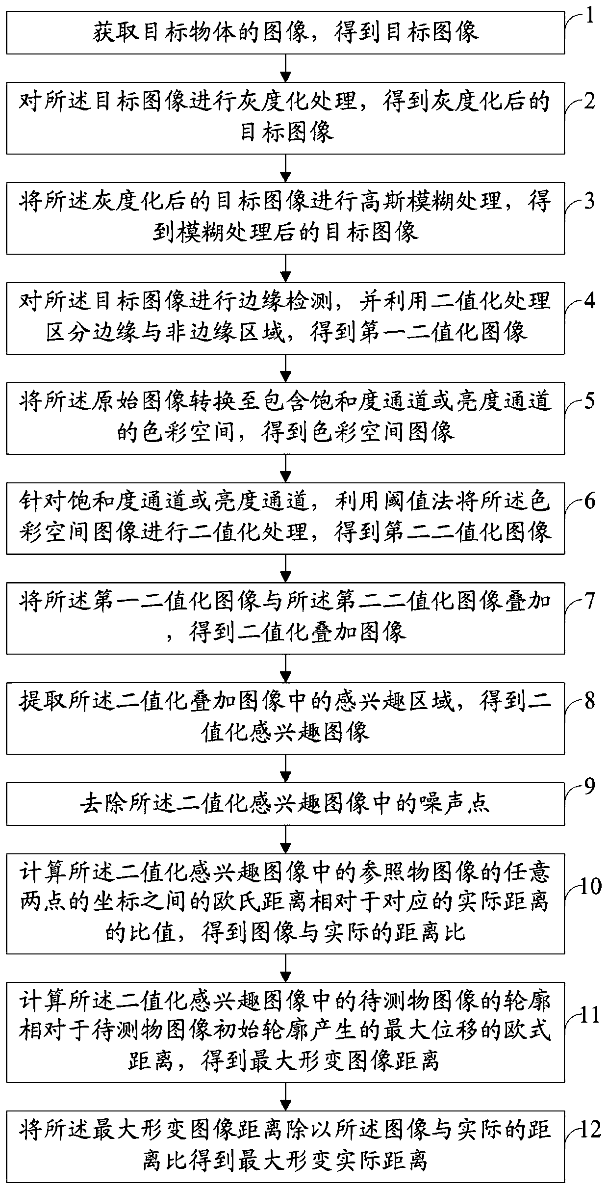
[0062] The following will clearly and completely describe the technical solutions in the embodiments of the present invention with reference to the accompanying drawings in the embodiments of the present invention. Obviously, the described embodiments are only some, not all, embodiments of the present invention. Based on the embodiments of the present invention, all other embodiments obtained by persons of ordinary skill in the art without making creative efforts belong to the protection scope of the present invention.

[0063] In order to make the above objects, features and advantages of the present invention more comprehensible, the present invention will be further described in detail below in conjunction with the accompanying drawings and specific embodiments.

[0064] The deformation monitoring method of the present invention is applied to a deformation monitoring device, which includes a single-board computer and a 4K distortion-free camera. The output end of the 4k dis...


PUM


Abstract

The invention discloses a deformation monitoring method and system. The method comprises the following steps of acquiring a target image including an object to be tested and a reference object; performing edge detection on the target image and performing binarization processing on the target image to obtain a first binarized image; converting a color space for the target image to obtain a color space image; for a saturation channel or a luminance channel, performing binarization processing on the color space image to obtain a second binarized image; superimposing the two binarized images to obtain a superimposed image; extracting a region of interest in the superimposed image to obtain an image of interest; calculating a ratio of the Euclidean distance between coordinates of any two pointsof a reference object image in the image of interest relative to the actual distance, and obtaining a distance ratio; calculating the Euclidean distance of the contour of an image of the object to betested relative to the maximum displacement of an initial contour in the image of interest, and obtaining a deformation image distance; and dividing the deformation image distance by the distance ratio to obtain a deformation actual distance. The deformation monitoring method provided by the invention can realize the deformation detection of objects under various working conditions and broaden the applicable range.

Description

technical field [0001] The invention relates to the field of deformation monitoring, in particular to a deformation monitoring method and system. Background technique [0002] Devices such as experimental devices, equipment or industrial equipment will be more or less deformed during the working process. Some deformation will affect the performance, safety and other factors of the device, so monitoring the degree of deformation is very important. [0003] Existing deformation monitoring methods include laser inspection. Specifically: place the laser, mounting frame, focusing lens, photodetector and oscilloscope in sequence, fix the measured object on the mounting frame, emit laser light, and adjust the position so that part of the spot is located on the cross-section of the measured object and part is located on the detector. , the deformation of the measured object will lead to the change of the luminous flux on the detector, which will cause the voltage change on the osc...

Claims


Application Information

Patent Timeline
IPC IPC(8): G01B11/16G06T7/11G06K9/62
CPCG01B11/16G06T7/11G06F18/2413
Inventor 王文伟张志鹏李宜丁
Owner BEIJING INSTITUTE OF TECHNOLOGYGY
Why Eureka
Try Eureka