
A dense busway

A busway and intensive technology, applied in the field of busway, can solve the problems of single installation method of busway, poor heat dissipation effect, inconvenient use, etc., and achieve good heat dissipation effect, convenient connection and convenient use

Active Publication Date: 2020-12-04
江苏隆鑫电气设备有限公司
View PDF7 Cites 0 Cited by
  • Summary
  • Abstract
  • Description
  • Claims
  • Application Information

AI Technical Summary

Problems solved by technology

[0002] The busway is a closed metal device composed of copper and aluminum busbar columns, which is used to distribute relatively high power to the various components of the decentralized system. When using high-power components, more conductive strips are used, so dense types are used. Busway, intensive busway is suitable for power supply and distribution systems of AC three-phase four-wire system, three-phase five-wire system, frequency 50-60Hz, rated voltage up to 690V, rated working current 250-5000A, as industrial and mining, enterprises and high-level Auxiliary equipment for power supply and distribution equipment in buildings, especially suitable for the transformation of workshops and old enterprises. In the prior art, the dense busway has a single way of installing busbar inserts, and the arrangement is messy, and it is not possible to choose multiple This method is used for installation, because the arrangement of the busbar sockets is relatively tight, resulting in poor heat dissipation, which leads to inconvenience in use. Therefore, we propose a dense busway

Method used


Image

  • A dense busway
  • A dense busway
  • A dense busway

Examples


Embodiment Construction

[0026] The following will clearly and completely describe the technical solutions in the embodiments of the present invention with reference to the accompanying drawings in the embodiments of the present invention. Obviously, the described embodiments are only some, not all, embodiments of the present invention. Based on the embodiments of the present invention, all other embodiments obtained by persons of ordinary skill in the art without making creative efforts belong to the protection scope of the present invention.

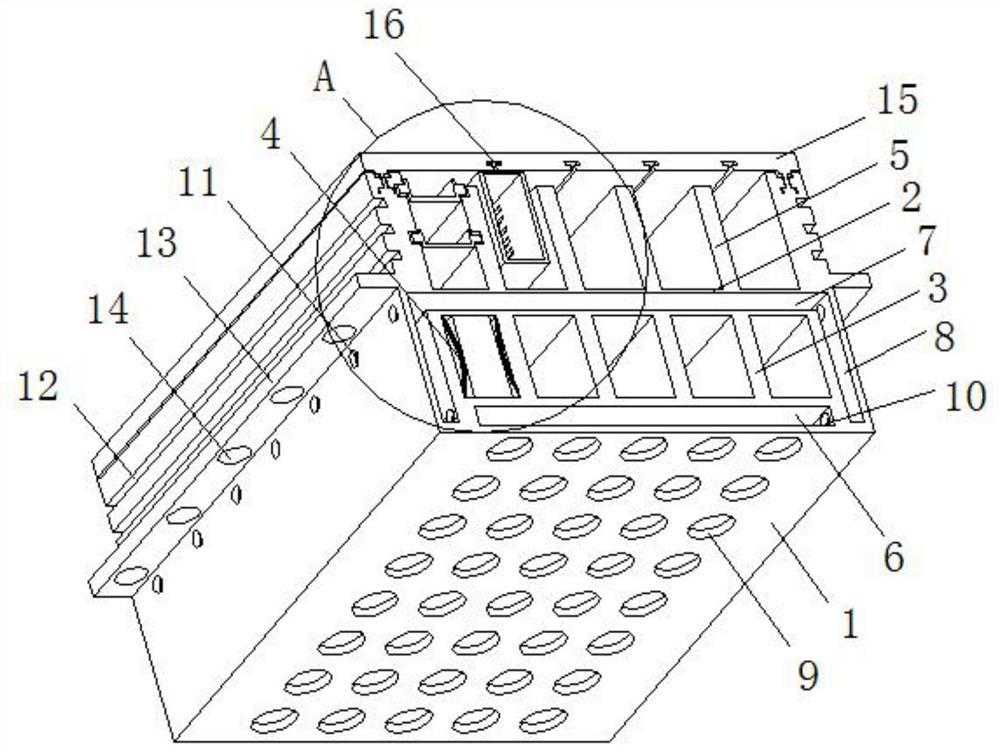
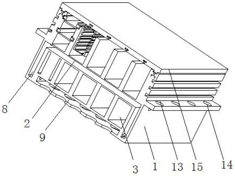
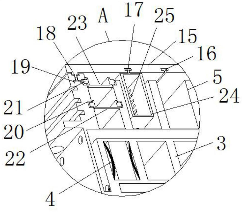
[0027] see Figure 1-3 , the present invention provides a technical solution: a dense busway, including a U-shaped shell 1, a card board 22 and a heat dissipation structure;

[0028] Shell 1: The interior of shell 1 is divided into the second installation area and the first installation area by the transverse partition 2, and the interior of the shell 1 is divided into the first installation area and the second installation area by the transverse partition 2, ...


PUM


Abstract

The invention discloses an intensive bus duct. The intensive bus duct comprises a U-shaped shell, a clamping plate and a heat dissipation structure, wherein the interior of the shell is divided into asecond installation area and a first installation area by a transverse partition plate up and down; the interior of the first installation area is uniformly divided into busbar installation grooves by a first vertical partition plate, and arc-shaped clamping pieces are correspondingly arranged on the left side walls and the right side walls of the busbar installation grooves; the second installation area is divided into busbar placement cavities through a second vertical partition plate; sliding grooves are correspondingly formed in the second vertical partition plate on the left side and theinner side wall of the shell; the two sides of the clamping plate are clamped between the sliding grooves in a sliding mode through sliding blocks; a mounting groove is formed in the surface of the clamping plate; the heat dissipation structure comprises a bottom through groove, an upper through groove, a side edge through groove and air inlet holes; and the bottom through groove is formed in themiddle part of the bottom plate of the shell. According to the intensive bus duct, busbars can be placed in a partition mode, the mounting modes are relatively more, the heat dissipation effect is relatively high, and the use is convenient.

Description

technical field [0001] The invention relates to the technical field of bus ducts, in particular to a dense bus duct. Background technique [0002] The busway is a closed metal device composed of copper and aluminum busbar columns, which is used to distribute relatively high power to the various components of the decentralized system. When using high-power components, more conductive strips are used, so dense types are used. Busway, intensive busway is suitable for power supply and distribution systems of AC three-phase four-wire system, three-phase five-wire system, frequency 50-60Hz, rated voltage up to 690V, rated working current 250-5000A, as industrial and mining, enterprises and high-level Auxiliary equipment for power supply and distribution equipment in buildings, especially suitable for the transformation of workshops and old enterprises. In the prior art, the dense busway has a single way of installing busbar inserts, and the arrangement is messy, and it is not poss...

Claims


Application Information

Patent Timeline
Patent Type & Authority Patents(China)
IPC IPC(8): H02G5/06H02G5/10
CPCH02G5/06H02G5/10
Inventor 方道宏黄磊方晰戴诚
Owner 江苏隆鑫电气设备有限公司
Learn More