
Phase-change heat dissipation motor shell and motor applying same

A technology of phase change and casing, applied in the direction of casing/housing/support, electrical components, electromechanical devices, etc., can solve the problems of phase change working fluid loss, reduced heat dissipation effect, poor heat dissipation continuity, etc., and achieve temperature dynamic balance , Improve the heat dissipation effect and avoid the effect of swelling

Pending Publication Date: 2019-07-26
UNIV OF ELECTRONICS SCI & TECH OF CHINA ZHONGSHAN INST
View PDF0 Cites 4 Cited by
  • Summary
  • Abstract
  • Description
  • Claims
  • Application Information

AI Technical Summary

Problems solved by technology

[0004] Aiming at the deficiencies of the prior art, the present invention provides a phase-change heat dissipation motor casing and a motor applied thereto, which solves the problem of poor heat dissipation continuity of general phase-change heat dissipation motors. As the temperature rises, the heat dissipation effect continues to decrease, and the phase change The fluidity of the working medium is poor, the space elasticity is small, and the loss of the phase change working medium is easy to occur

Method used


Image

  • Phase-change heat dissipation motor shell and motor applying same
  • Phase-change heat dissipation motor shell and motor applying same
  • Phase-change heat dissipation motor shell and motor applying same

Examples


Embodiment Construction

[0025] The following will clearly and completely describe the technical solutions in the embodiments of the present invention in conjunction with the accompanying drawings of the present invention. Obviously, the described embodiments are only some, not all, embodiments of the present invention. Based on the embodiments of the present invention, all other embodiments obtained by persons of ordinary skill in the art without making creative efforts belong to the protection scope of the present invention.

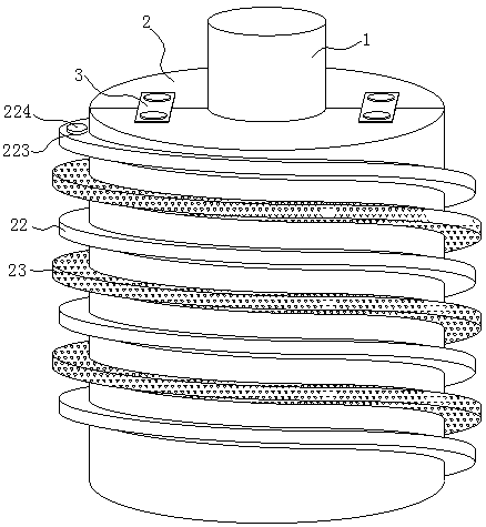
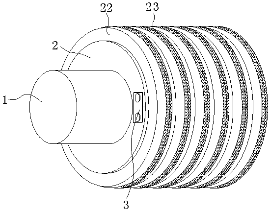
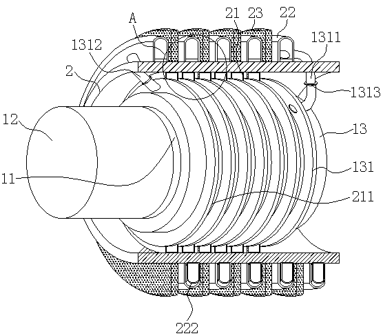
[0026] Such as Figure 1-4 As shown, the embodiment of the present invention provides a phase change heat dissipation motor casing and a motor for its application, including a motor body 1 and a casing shell 2. The motor body 1 includes a rotor assembly 11, a rotating shaft 12 and a stator assembly 13, and the rotating shaft 12 One end is fixedly connected with the rotor assembly 11 through a bearing, the rotor assembly 11 is sleeved inside the stator assembly 13, the stator a...


PUM


Abstract

The invention provides a phase-change heat dissipation motor shell and a motor applying the same. The phase-change heat dissipation motor shell comprises a motor body and a motor shell, wherein the motor body comprises a rotor assembly, a rotating shaft and a stator assembly; one end of the rotating shaft is fixedly connected with the rotor assembly through a bearing; the rotor assembly is arranged in the stator assembly in a sleeved mode; the stator assembly is arranged inside the motor shell in a sleeved mode; and spiral phase-change cooling fins are fixedly connected to the surface of the stator assembly. The invention relates to the field of motors. According to the phase-change heat dissipation motor shell and the motor applying the same, the integrated spiral heat dissipation structure is used, and compared with an existing independent heat dissipation fins, the flowing space of the phase-change working medium is large, the heat dissipation continuity is enhanced, and meanwhile,the heat dissipation effect of the traditional fan-shaped heat fins is enhanced on the basis, and the consumable material of the machine shell is saved, so that the problems that the heat dissipationcontinuity of a common phase-change heat dissipation motor is poor, the heat dissipation effect is continuously reduced along with the increase of temperature, and the phase-change working medium is poor in liquidity and small in space elasticity and phase-change working medium loss occurs easily can be solved.

Description

technical field [0001] The invention relates to the technical field of motors, in particular to a phase-change heat dissipation motor casing and a motor applied thereto. Background technique [0002] The current heat dissipation method of the motor is mainly that the surface of the motor casing is provided with heat dissipation fins, the heat of the motor components is transferred to the motor casing through the heat transfer medium, and then the heat dissipation fins of the casing gather the heat and dissipate it to achieve heat dissipation. The effect of this kind of heat dissipation is relatively common. In order to achieve a good heat dissipation effect, it is necessary to expand the heat dissipation area. Therefore, such a motor casing is set larger, and the heat transfer effect is poor after heat balance. Heat dissipation, but the fluidity of the phase change working medium is poor in a small space, and the heat dissipation efficiency is low, and when the phase change ...

Claims


Application Information

Patent Timeline
IPC IPC(8): H02K5/18H02K5/20H02K9/08H02K9/19
CPCH02K5/18H02K5/20H02K9/08H02K9/19
Inventor 杨亮夏百庆戚远航
Owner UNIV OF ELECTRONICS SCI & TECH OF CHINA ZHONGSHAN INST
Learn More