Battery temperature control system and method

A battery temperature control and battery cabinet technology, applied in secondary batteries, circuits, electrical components, etc., can solve the problems of inconsistent battery capacity, low temperature control efficiency, battery capacity attenuation, etc., to improve temperature control flexibility, improve System performance, effect of reducing temperature differences

Active Publication Date: 2021-05-04
BYD CO LTD +1
View PDF9 Cites 4 Cited by
  • Summary
  • Abstract
  • Description
  • Claims
  • Application Information

AI Technical Summary

Problems solved by technology

[0005]First, this kind of energy storage cabinet only considers the temperature rise of the battery during operation to cool the surroundings of the battery. More and more diverse, energy storage cabinets often need to supply power in severe cold regions, which makes the energy storage cabinet batteries in related technologies work at low temperature for a long time to accelerate battery capacity decay
[0006]Secondly, after cooling the battery in the energy storage cabinet, the gas still stays around the battery, resulting in the ineffective cooling effect, which often requires the cooling device to increase the power to work. Achieve ideal cooling effect
[0007]Thirdly, the cooling device of this kind of energy storage cabinet generally transports cooling gas from top to bottom, because the heat generated by the battery at the upper end of the cabinet has absorbed the cold The cooling capacity of the battery at the bottom of the cabinet is very small, resulting in a large temperature difference between the upper and lower batteries. Long-term operation of the battery module will result in inconsistent capacity of the upper and lower batteries, which will affect the overall performance of the system.
[0008] It can be seen that the energy storage cabinets in the prior art have the problems of not being flexible enough to control the temperature of the battery, and the temperature control efficiency is not high

Method used


Image

  • Battery temperature control system and method
  • Battery temperature control system and method
  • Battery temperature control system and method

Examples


Embodiment Construction

[0051] In order to make the above objects, features and advantages of the present invention more comprehensible, the present invention will be further described in detail below in conjunction with the accompanying drawings and specific embodiments.

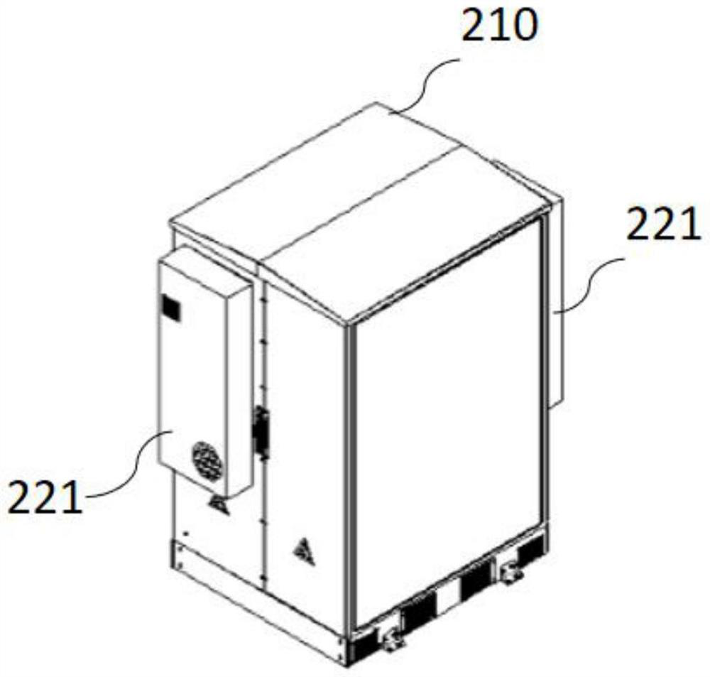
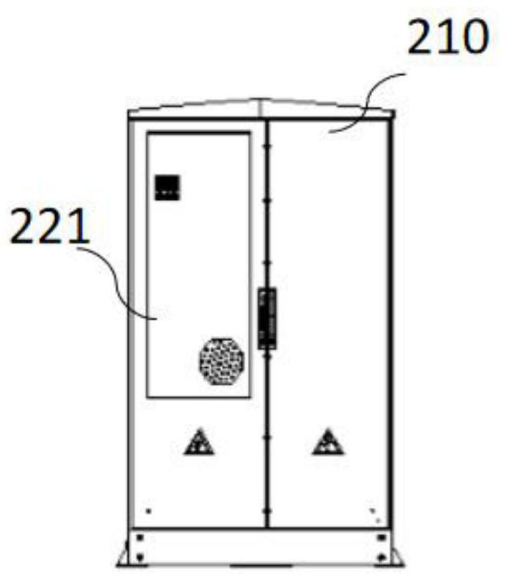
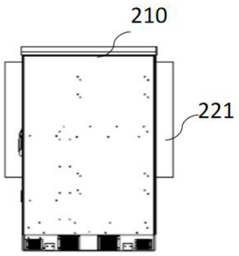
[0052] When the applicant conceived the technical solution of the present application, he found that the energy storage cabinet in the related art had the following disadvantages: in the low temperature environment such as severe cold, the battery cannot be heated to maintain the performance of the battery; When the lower input is supplied to the battery module, the battery module at the lower end cannot obtain enough cooling air, resulting in a large difference in cooling between the upper and lower battery modules; When the battery temperature is normal, it is impossible to quickly adjust the temperature difference between the battery modules, that is, it is impossible to ensure that the temperature of each battery module maintai...


PUM


Abstract

The invention discloses a battery temperature control system and method. The system comprises a battery cabinet body, a microcontroller, a temperature adjusting device, a ventilation wall and at least one battery module, wherein the microcontroller is connected with the temperature adjusting device; the battery modules are sequentially installed in the battery cabinet body from top to bottom; the microcontroller is used for controlling the temperature adjusting device to output cold air to each battery module from top to bottom through the ventilation wall when the battery module with the temperature exceeding a first preset value exists so as to cool each battery module is cooled; and the microcontroller is also used for controlling the temperature adjusting device to output hot air to each battery module from top to bottom through the ventilation wall when a battery module with a temperature lower than or equal to a second preset value exists so as to heat each battery module. The battery temperature control system can be used for cooling and heating the battery module, and has strong adaptive capacity to the environment.

Description

technical field [0001] The invention relates to the technical field of battery temperature control of an energy storage cabinet, in particular to a battery temperature control system and a battery temperature control method. Background technique [0002] At present, battery energy storage systems are more and more widely used in new energy, smart grid, energy-saving technology and other fields from power generation to power consumption. Grid-connected capacity of renewable energy. [0003] Taking the energy storage cabinet as an example, the energy storage cabinet is an important part of the battery energy storage system, and the power battery included in it is greatly affected by temperature. When working in the environment, irreversible reactions will occur inside the power battery itself, which reduces the overall performance of the energy storage cabinet; when the temperature of the lithium-ion power battery reaches the ignition point of the internal materials of the po...

Claims


Application Information

Patent Timeline
Patent Type & Authority Applications(China)
IPC IPC(8): H01M10/613H01M10/615H01M10/627H01M10/635H01M10/6563H01M10/6565H01M10/6566
CPCH01M10/613H01M10/627H01M10/635H01M10/6563H01M10/615H01M10/6565H01M10/6566Y02E60/10
Inventor 蒋宝超马明君孙嘉品
Owner BYD CO LTD
Why Eureka
Try Eureka