
Tail door pushing rod outer pipe fixing structure

A technology of fixing structure and outer tube, applied in door/window fittings, building structure, power control mechanism, etc., can solve the problems of complicated push rod assembly, easy connection failure, large workload, etc., to achieve simple and convenient assembly, prevent The effect of good rotation and convenient assembly

Pending Publication Date: 2019-07-30
DONGYANG GANTE ELECTRICAL CO LTD
View PDF0 Cites 2 Cited by
  • Summary
  • Abstract
  • Description
  • Claims
  • Application Information

AI Technical Summary

Problems solved by technology

[0003] Some in-line push rods have very long outer tubes, and the axial length of the outer tube is greater than the axial length of the motor part plus the screw rod part. Because the outer tube is very long, the assembly of the push rod is very troublesome and inconvenient for assembly line assembly; When the outer tube needs to be assembled, the ball head, motor, reduction mechanism, screw, bearing and other parts need to be assembled at the same time, and the workload of a single station will be very large
And the outer tube may be rotated, the connection between the outer tube and the ball head is prone to failure, and the waterproof effect is poor

Method used


Image

  • Tail door pushing rod outer pipe fixing structure
  • Tail door pushing rod outer pipe fixing structure
  • Tail door pushing rod outer pipe fixing structure

Examples


Embodiment 1

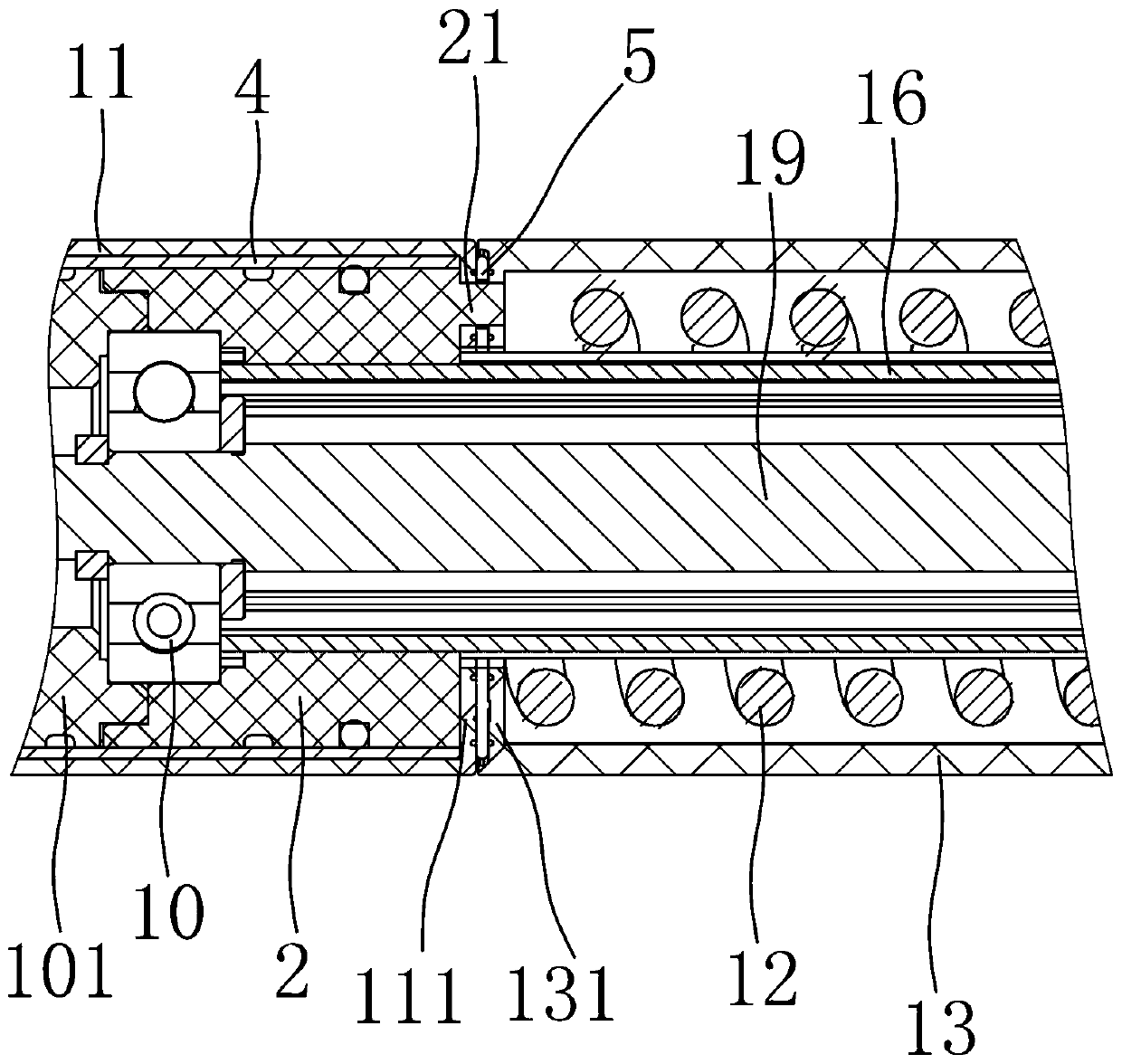
[0040] Depend on Figure 1 to Figure 6 As shown, a tailgate push rod outer tube fixing structure of the present invention includes a motor outer tube 1 for accommodating the driving part, a spring outer tube 13 for protecting the compression spring 12 and a top tube outer tube 14, The conduit 16 used to guide the screw nut 15, the top tube 17 fixed to the screw nut 15, the end of the top tube 17 away from the screw nut 15 is fixed with a first ball head assembly 18, and one end of the screw rod 19 passes through the bearing 10 is fixed in the motor outer tube 11, the jacking tube outer tube 14 is sleeved outside the jacking tube 17 and fixed with the first ball head assembly 18, the spring outer tube 13 and the jacking tube outer tube 14 are mutually sleeved, and the spring outer tube 13 There is a seal between the jacking pipe outer tube 14, and the end of the motor outer tube 11 close to the spring outer tube 13 is provided with a guide sleeve 2, and the end of the guide tub...

Embodiment 2

[0048] The difference between this embodiment and Embodiment 1 is that, except for the seal, other structures of this embodiment are the same as those in Embodiment 1.

[0049] Depend on Figure 11 to Figure 14 As shown, in the spring outer tube 13 and the jacking tube outer tube 14 that are nested with each other, the spring outer tube 13 is a plastic tube, the jacking tube outer tube 14 is a metal tube, and a seal is provided between the spring outer tube 13 and the jacking tube outer tube 14. 70 pieces. The seal includes a fixed sleeve 71 and a rubber sleeve 72 fixed on the fixed sleeve 71. The rubber sleeve 72 is glued and fixed on the circumferential inner side of the fixed sleeve 71, and the rubber sleeve 72 is formed on the circumferential surface of the side away from the fixed sleeve 71. The sealing protruding ring 73, several sealing protruding rings 73 are arranged at intervals along the axial direction, the spring outer tube 13 is fixed with the fixing sleeve 71 o...

Embodiment 3

[0054] The difference between this embodiment and Embodiment 1 is that, except for the seal, other structures of this embodiment are the same as those in Embodiment 1; the difference between this embodiment and Embodiment 1 lies in the difference between the seal and the spring outer tube.

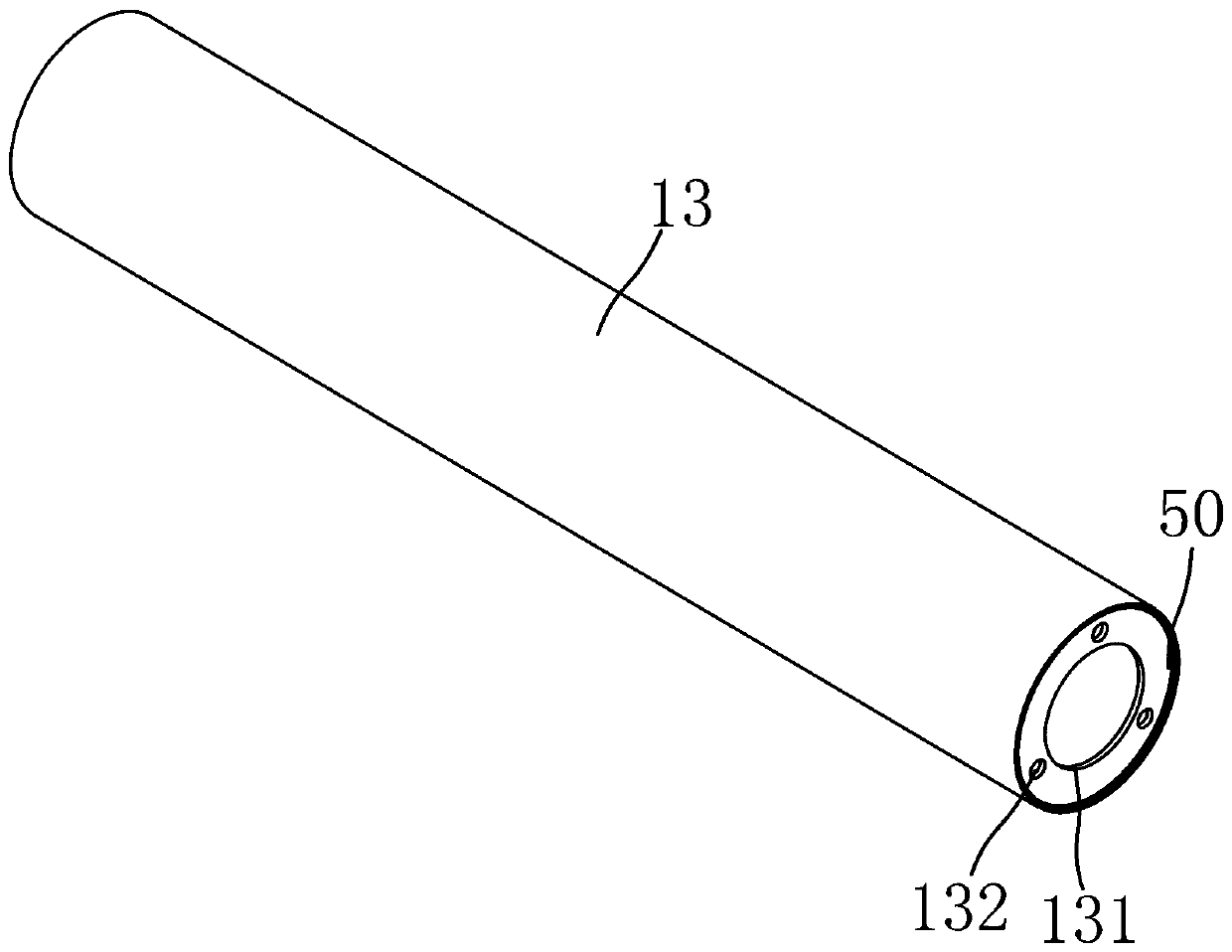
[0055] Depend on Figure 15 to Figure 19 As shown, in the spring outer tube 13 and the jacking tube outer tube 14 that are nested with each other, the spring outer tube 13 is a plastic tube, and the jacking tube outer tube 14 is a metal tube. The seal 80 is fixed to the spring outer tube 13 . A plurality of annular grooves 131 are formed on the inner wall of the spring outer tube 13. The plurality of annular grooves 131 are arranged at intervals along the axis of the spring outer tube 13. The sealing member 80 includes a metal part 81 and a colloid 82 coated on the metal part 81. The colloid 82 is annular , the circumferential outer edge part of the colloid 82 wraps the metal part 81 and ...


PUM


Abstract

The invention aims to provide a tail door pushing rod outer pipe fixing structure convenient to assemble and capable of avoiding outer pipe rotation. In order to achieve the purpose, the following technical scheme is adopted: the tail door pushing rod outer pipe fixing structure comprises a motor outer pipe, a spring outer pipe, a jacking pipe outer pipe, a guiding pipe and a jacking pipe; a firstball head assembly is fixed to the end, away from a lead screw nut, of the jacking pipe; one end of a lead screw is fixed into the motor outer pipe through a bearing; a guiding pipe sleeve is arranged at the end, close to the spring outer pipe, of the motor outer pipe, and two or more positioning bulges are arranged on the axial face of the guiding pipe sleeve or the motor outer pipe; the end, close to the motor outer pipe, of the spring outer pipe is provided with a first inner convex ring which is provided with a plurality of first positioning grooves corresponding to the positioning bulges; and a compression spring is located between the guiding pipe and the spring outer pipe, one end of the compression spring abuts against the axial face of the first inner convex ring, and the other end of the compression spring abuts against the first ball head assembly.

Description

technical field [0001] The invention relates to a tailgate push rod, in particular to a fixing structure for an outer tube of a tailgate push rod. Background technique [0002] Tailgate push rods include one-shaped (motor output shaft is coaxial with the screw rod) and L-shaped (motor output shaft is parallel to the screw rod). [0003] Some in-line push rods have very long outer tubes, and the axial length of the outer tube is greater than the axial length of the motor part plus the screw rod part. Because the outer tube is very long, the assembly of the push rod is very troublesome, and it is not convenient for assembly line assembly; When it is necessary to assemble the outer tube, the ball head, motor, reduction mechanism, screw, bearing and other components need to be assembled at the same time, and the workload of a single station will be very large. Moreover, the outer tube may be rotated, the connection between the outer tube and the ball head is prone to failure, a...

Claims


Application Information

Patent Timeline
Patent Type & Authority Applications(China)
IPC IPC(8): E05F15/622
CPCE05F15/622E05Y2900/548E05Y2600/60
Inventor 马耀辉朱炎钊蔡桥洪
Owner DONGYANG GANTE ELECTRICAL CO LTD
Learn More