
Fractional Amplitude Interferometer Based on 2.02μm Single Longitudinal Mode Laser

A single longitudinal mode, amplitude type technology, applied in the optical field, can solve the problems of low transmittance, difficult to measure the refractive index uniformity of crystals, etc., and achieve the effects of wavelength stability, high stability, output power and mode stability.

Active Publication Date: 2021-09-17
HARBIN INST OF TECH
View PDF9 Cites 0 Cited by
  • Summary
  • Abstract
  • Description
  • Claims
  • Application Information

AI Technical Summary

Problems solved by technology

[0004] The purpose of the present invention is to solve the existing problem that the transmittance of 632.8nm is low, but the crystal with high transmittance of 2.02μm is difficult to measure the uniformity of the refractive index, and provides a sub-amplitude interferometer based on a 2.02μm single longitudinal mode laser

Method used


Image

  • Fractional Amplitude Interferometer Based on 2.02μm Single Longitudinal Mode Laser

Examples


specific Embodiment approach 1

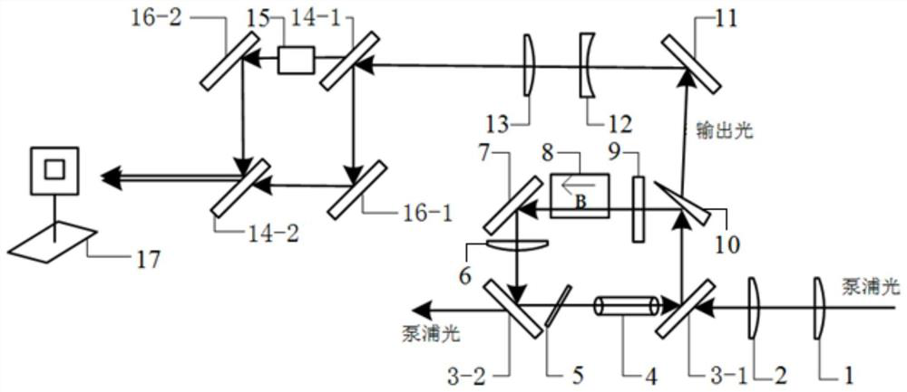
[0022] Specific implementation mode one: the following combination figure 1 This embodiment is described. The amplitude-divided interferometer based on a 2.02 μm single longitudinal mode laser in this embodiment includes a first plano-convex lens 1, a second plano-convex lens 2, a first dichroic mirror 3-1, and a second dichroic mirror 3- 2. Tm: LuAG crystal 4, F-P etalon 5, third plano-convex lens 6, first reflector 7, Faraday rotator 8, half-wave plate 9, wedge output mirror 10, second reflector 11, plano Concave lens 12, fourth plano-convex lens 13, first beam splitter 14-1, second beam splitter 14-2, third mirror 16-1, fourth mirror 16-2 and laser beam analyzer 17;

[0023] The plane of the first plano-convex lens 1 is opposite to the convex surface of the second plano-convex lens 2, forming a No. 1 coupling system;

[0024] The plane of the plano-convex lens 12 is opposite to the convex surface of the fourth plano-convex lens 13, forming the No. 2 coupling system;

[00...

specific Embodiment approach 2

[0047] Specific embodiment 2: The difference between this embodiment and specific embodiment 1 is: the light-transmitting surfaces of the first plano-convex lens 1 and the second plano-convex lens 2 are coated with a 788nm high-transparency film, and the focal length is 10 mm to 1000 mm. 10mm-100mm; the light-passing surface of the third plano-convex lens 6 is coated with a 2.02μm anti-reflection coating, and the focal length is 10mm-1000mm. Others are the same as in the first embodiment.

specific Embodiment approach 3

[0048] Specific embodiment three: this embodiment is different from one of specific embodiments one or two in that: the first dichroic mirror 3-1 and the second dichroic mirror 3-2 are coated with a 788nm anti-reflection film on one side, and the other One side is coated with 788nm AR coating and 2.02μm AR coating. Others are the same as in the first or second embodiment.


PUM

PropertyMeasurementUnit
lengthaaaaaaaaaa
diameteraaaaaaaaaa
thicknessaaaaaaaaaa

Abstract

The sub-amplitude interferometer based on a 2.02μm single longitudinal mode laser relates to a sub-amplitude interferometer, which belongs to the field of optics and solves the problem of existing crystals with low transmittance at 632.8nm but high transmittance at 2.02μm. The problem of measuring refractive index homogeneity. Amplitude-divided interferometer based on 2.02μm single longitudinal mode laser: the plane of the first plano-convex lens is opposite to the convex surface of the second plano-convex lens, forming the No. 1 coupling system; the plane of the plano-concave lens is opposite to the convex surface of the fourth plano-convex lens, forming the second No. coupling system; first dichroic mirror, second dichroic mirror, Tm:LuAG crystal, F‑P etalon, third plano-convex lens, first mirror, Faraday rotator, half-wave plate and wedge output The mirror constitutes a 2.02 μm single longitudinal mode laser; the first beam splitter, the second beam splitter, the third reflector, the fourth reflector and the laser beam analyzer form an amplitude-splitting interference optical path with the crystal to be measured.

Description

technical field [0001] The invention relates to a sub-amplitude interferometer, which belongs to the field of optics. Background technique [0002] Medium and long-wave infrared lasers in the 3μm-5μm band and 8μm-10μm band can be used in remote sensing, photoelectric countermeasures, spectroscopy, material processing, and medicine, especially in military fields such as infrared detection and infrared thermal imaging. is widely used. The most effective way to obtain mid- and long-wavelength lasers is to down-convert the frequency of 2μm-band lasers through an optical parametric oscillator (OPO). [0003] Cadmium selenide (CdSe) crystals and zinc germanium phosphorus (ZnGeP 2 ) crystals are commonly used nonlinear crystals for 3-5 μm and 8-10 μm bands. The quality of the crystal will directly affect the power and beam quality of the output laser. Among them, the uniformity of crystal refractive index is an important indicator to measure the quality of crystal growth. Interf...

Claims


Application Information

Patent Timeline
Patent Type & Authority Patents(China)
IPC IPC(8): G01N21/45
CPCG01N21/45
Inventor 姚宝权密淑一刘高佑戴通宇段小明
Owner HARBIN INST OF TECH
Learn More