Method for detecting tunnel overlying formation cavities and uncompacted areas

A technology for stratum cavities and tunnels, which is applied in engineering geophysical prospecting and tunnel engineering fields, can solve problems such as unsatisfactory detection results, high cost, and time-consuming construction, and achieve the effects of convenient testing, low cost, and avoiding interference

Pending Publication Date: 2019-07-30
中铁西南科学研究院有限公司
View PDF5 Cites 0 Cited by
  • Summary
  • Abstract
  • Description
  • Claims
  • Application Information

AI Technical Summary

Problems solved by technology

Ground-penetrating radar and electrical detection methods are both severely interfered by metals. For subway construction with dense underground pipelines, the detection effect is not ideal; cross-hole tomography is a relatively mature technical means with high resolution and reliability. Good performance and intuitive images, but it needs to be carried out with the help of drilling holes, so the construction is time-consuming and costly

Method used


Image

  • Method for detecting tunnel overlying formation cavities and uncompacted areas
  • Method for detecting tunnel overlying formation cavities and uncompacted areas
  • Method for detecting tunnel overlying formation cavities and uncompacted areas

Examples


Embodiment 1

[0046] Embodiment 1, for as Figure 5The theoretical numerical model is shown for inversion imaging. The size of the model is 50m and 50m in the horizontal and vertical directions, respectively. In order to be close to the actual geological model, the theoretical numerical model is set as follows: the burial depth of the overlying strata of the tunnel is set to 0m-19.5m; the upper and lower interfaces of the tunnel lining are respectively set, and the burial depth of the upper interface of the lining is 19.5m-20.5m. The buried depth of the lower interface is 29.5m-30.5m; the buried depth of the tunnel space layer is 20.5m-29.5m; the buried depth of the underlying bedrock layer of the tunnel is 30.5m-50m, and the velocity and density values ​​set for each layer are detailed in the table 1. Example 1 is a model without anomalies, that is, the stratum overlying the tunnel is set as a homogeneous medium, and the velocity values ​​are the same. The source points are located on t...

Embodiment 2

[0048] Embodiment 2, adopt as Figure 8 The anomaly model with holes is shown. The size of the model, the distribution of dielectric layers, the location and quantity of seismic sources and geophones are all the same as those in Embodiment 1 above. In addition, a cavity anomaly with a diameter of 2m is set in the overlying strata of the tunnel. The anomaly is located at the lateral position of the model at 24-26m and the longitudinal position at 9-11m. The set anomaly model P-wave velocity value is 340m / s.

[0049] According to the method of the present invention, the model is sequentially excited by seismic waves, the data is collected by the geophone (group) and the seismic wave reflection CT inversion imaging is performed, Figure 9 The initial model input for the inversion in this embodiment is consistent with the initial input model in Example 1, and the resulting characteristic map obtained by inversion imaging is as follows Figure 10 shown. It can be seen from the f...


PUM


Abstract

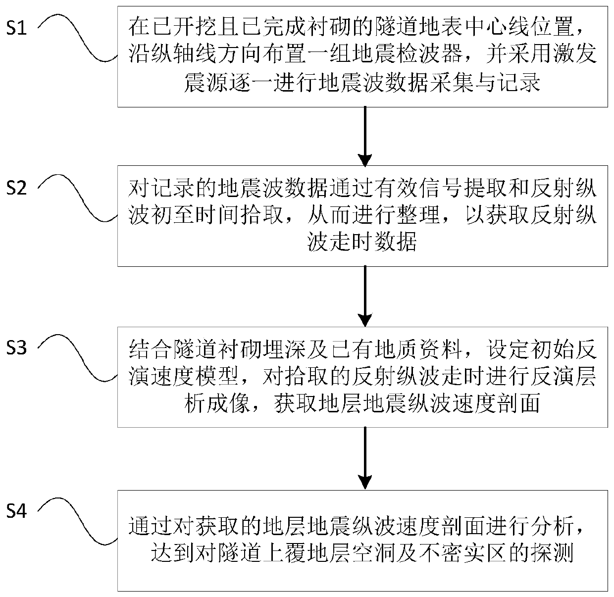
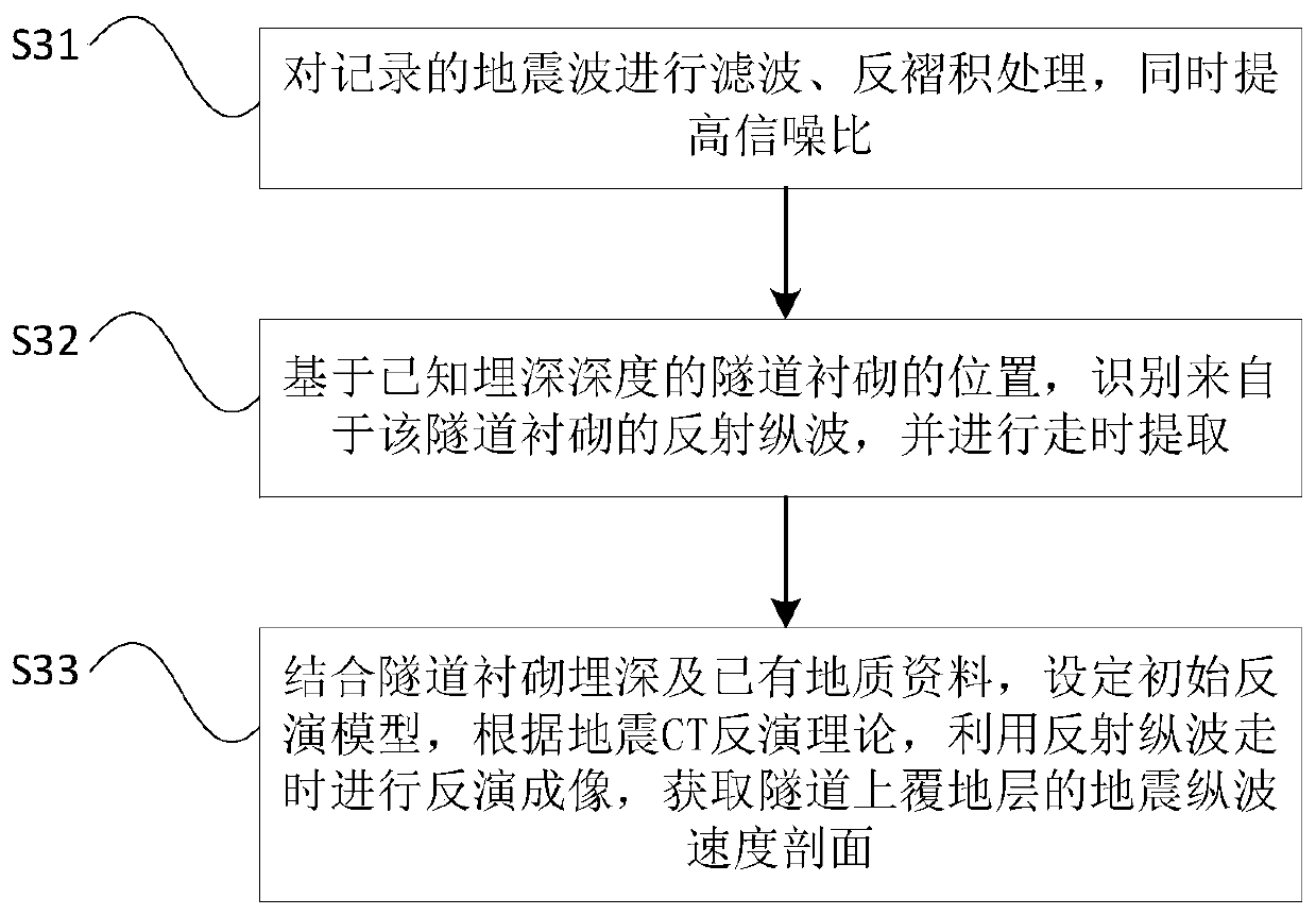
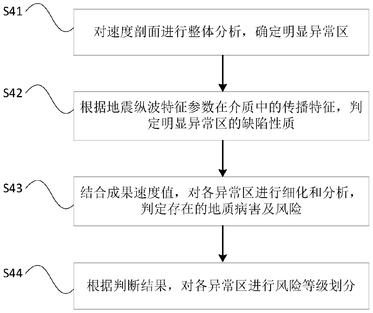
The invention discloses a method for detecting tunnel overlying formation cavities and uncompacted areas. The method comprises the following steps: at a ground surface central line position of an excavated tunnel of which lining is completed, arranging a group of geophones along an axis direction, and gradually performing earthquake wave data acquisition and recording one by one through an excitation source; tidying the recorded earthquake wave data through effective signal extraction and reflected P-wave first arrival time picking up, thereby obtaining reflected P-wave travel time data; in combination with tunnel lining cover depth and an underground stratum speed interval reflected by the existing geological data, setting an initial inversion speed model, performing inversion tomographyfor the reflected P-wave picked up, and acquiring a stratum earthquake P-wave speed profile; analyzing the acquired stratum earthquake P-wave speed profile, thereby realizing detection of tunnel overlying formation cavities and uncompacted areas. By the scheme above, the method achieves an aim of being simple in structure, smart in design and convenient and efficient for testing, and has very highpractical value and promotional value.

Description

technical field [0001] The invention belongs to the technical field of tunnel engineering and engineering geophysical prospecting, and in particular relates to a method for detecting voids and looseness of stratum overlying a tunnel. Background technique [0002] With the development of cities, the safety problems in my country's subway construction have become increasingly prominent. Common accidents caused by the construction of subways include: landslides, tilting of surrounding buildings, damage to underground pipelines, etc. Among them, ground collapse accidents account for a large proportion. Ground collapse has the characteristics of suddenness, complexity and high hazard. Once a ground collapse accident occurs , not only cause huge economic and property losses, produce bad social impact, but also seriously threaten the safety of people's lives. [0003] Practice has shown that the subway shield method construction or underground excavation will disturb the stratum, ...

Claims


Application Information

Patent Timeline
Patent Type & Authority Applications(China)
IPC IPC(8): G01V1/30
CPCG01V1/306
Inventor 卢松汪旭李苍松孟露李春林胡鹏张海超赵占群张优彭跃
Owner 中铁西南科学研究院有限公司
Why Eureka
Try Eureka