A differential mode-locked laser phase-locked loop

A mode-locked laser and phase-locked loop technology, applied in the electronic field, can solve the problems of phase lag, phase-locked loop oscillation, and low upper limit of phase-locked loop bandwidth

Active Publication Date: 2020-07-17
UNIV OF ELECTRONICS SCI & TECH OF CHINA
View PDF4 Cites 0 Cited by
  • Summary
  • Abstract
  • Description
  • Claims
  • Application Information

AI Technical Summary

Problems solved by technology

Therefore, the requirement for system stability makes the upper limit of the locking bandwidth of the phase-locked loop limit the improvement limit of the locking bandwidth
[0004] For a practical passive differential mode-locked laser PLL, the piezoelectric transducer and its high-voltage driver in the system have time delay and resonance characteristics, which introduce an additional phase lag in the loop, limiting the PLL's performance. bandwidth cap
In this case, due to the low upper limit of the PLL bandwidth, once the loop gain is increased so that the locked bandwidth is higher than the upper limit of the bandwidth, it will cause the PLL to oscillate or lose lock
Therefore, in a passive mode-locked laser phase-locked loop system with only proportional-integral loop filters, the phase lag introduced by its piezoelectric transducer and high-voltage driver limits the upper limit of its locking bandwidth, thereby limiting Potential of Phase Loop Locking Bandwidth to Improve Output Optical Pulse Signal Stability and Timing Jitter Performance

Method used


Image

  • A differential mode-locked laser phase-locked loop
  • A differential mode-locked laser phase-locked loop
  • A differential mode-locked laser phase-locked loop

Examples


Embodiment Construction

[0026] The specific embodiments of the present invention are described below so that those skilled in the art can understand the present invention, but it should be clear that the present invention is not limited to the scope of the specific embodiments. For those of ordinary skill in the art, as long as various changes Within the spirit and scope of the present invention defined and determined by the appended claims, these changes are obvious, and all inventions and creations using the concept of the present invention are included in the protection list.

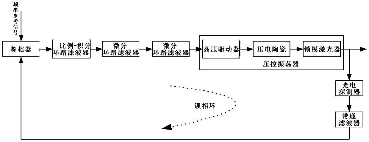
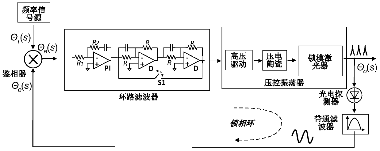
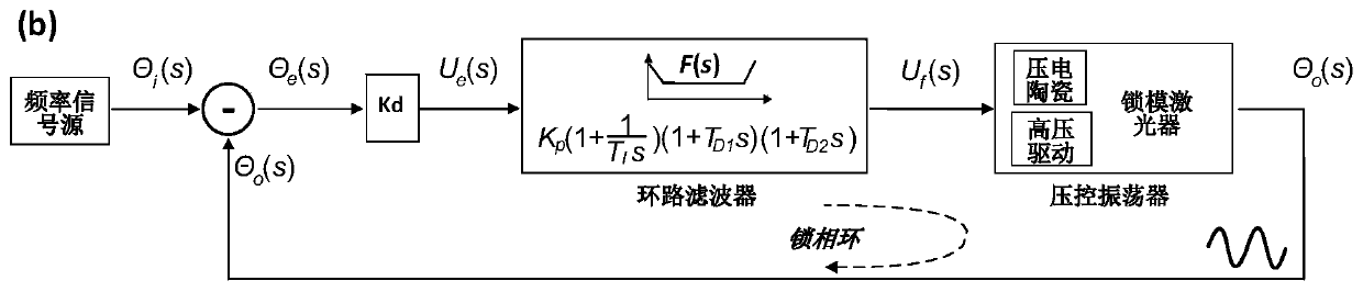
[0027] Such as figure 1 with figure 2 As shown, the differential mode-locked laser phase-locked loop includes:

[0028] The photodetector is used to convert the optical pulse signal output by the mode-locked laser into an electrical signal;

[0029] A band-pass filter is used to filter out noise in the electrical signal to form a microwave signal;

[0030] A phase detector is used to mix the microwave signal output by t...


PUM


Abstract

The invention discloses a differential mode-locked laser phase-locked loop, which comprises a phase detector, a proportional-integral loop filter, a differential loop filter module, a voltage-controlled oscillator, a photoelectric detector, and a band-pass filter connected in sequence. device, the bandpass filter is connected to the phase detector. The present invention proposes a multiple differential loop filter phase-locked loop scheme, in which two or more differential loop filters are used to compensate the phase lag brought by the piezoelectric transducer and the high-voltage driver; thereby the The upper limit of the phase-locked loop bandwidth is increased by more than an order of magnitude, which greatly expands the improvement space of its phase-locked bandwidth while ensuring the stability of the phase-locked loop.

Description

technical field [0001] The invention relates to the field of electronic technology, in particular to a differential mode-locked laser phase-locked loop. Background technique [0002] As an ultrashort pulse laser source, passive mode-locked lasers (MLLs) have been widely used in the fields of optical / RF frequency standard generation, photonic radar, optical communication, ultra-low noise microwave synthesis, precision time-frequency metrology, and time-frequency distribution. These applications require the use of a phase-locked loop to lock the passive mode-locked laser to a high-stability optical or microwave frequency standard source, so that the phase and repetition rate of the passive mode-locked laser can be locked to the high-stability frequency standard source through the phase-locked loop . [0003] The locking bandwidth of the phase-locked loop is defined as the corresponding system frequency when the open-loop loop gain amplitude of the phase-locked loop is 0dB. As...

Claims


Application Information

Patent Timeline
Patent Type & Authority Patents(China)
IPC IPC(8): H01S3/098
CPCH01S3/1112
Inventor 侯冬白清松
Owner UNIV OF ELECTRONICS SCI & TECH OF CHINA
Why Eureka
Try Eureka