Decoration material cutting machine

A technology for cutting machines and cutting knives, which is applied in the direction of shearing devices, accessories of shearing machines, metal processing machinery parts, etc. It can solve the problems that affect the user's experience of using cutting machines for decoration materials, and achieve low noise and shock absorption effects Good results

Inactive Publication Date: 2019-08-02
王亢
View PDF5 Cites 7 Cited by
  • Summary
  • Abstract
  • Description
  • Claims
  • Application Information

AI Technical Summary

Problems solved by technology

[0004] However, although the decoration material cutting machine has a certain dust removal function, due to its relatively simple dust removal structure, the decoration material cutting machine will still emit a large amount of dust when it is working. Experience

Method used


Image

  • Decoration material cutting machine
  • Decoration material cutting machine
  • Decoration material cutting machine

Examples


Embodiment 1

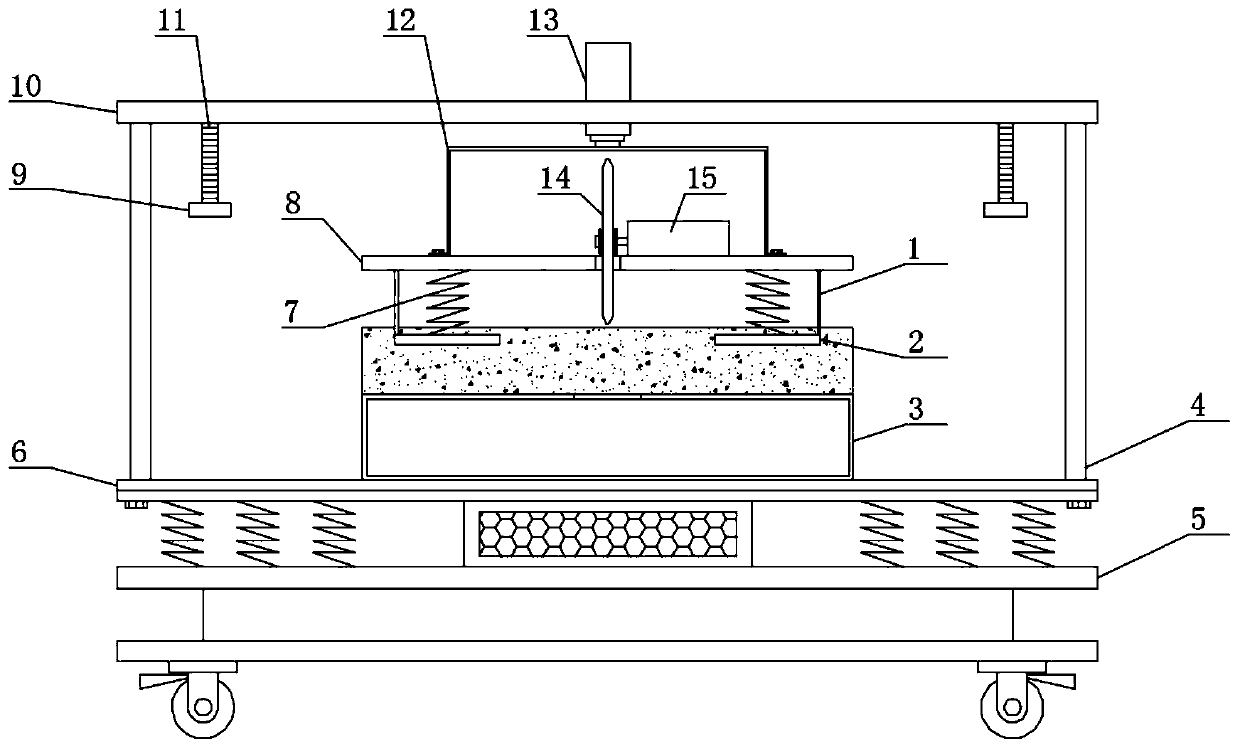
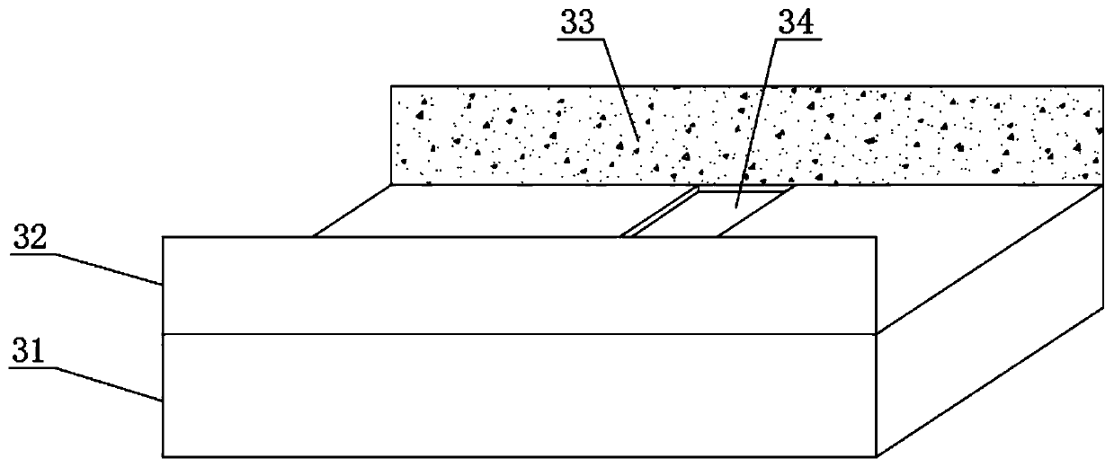
[0025] see Figure 1-Figure 3 , the present invention provides a technical solution: a cutting machine for decoration materials, including a support base plate 6, a support top plate 10 is arranged above the support base plate 6, a bracket 4 is provided at the connection between the support base plate 6 and the support top plate 10, and the support top plate 10 A hydraulic cylinder 13 is provided through the middle of the hydraulic cylinder 13, a first support plate 8 is provided below the hydraulic cylinder 13, a dust cover 12 is provided at the connection between the first support plate 8 and the hydraulic cylinder 13, and one end of the upper surface of the first support plate 8 Drive motor 15 is provided, and the output end of drive motor 15 is provided with cutting knife 14, and the upper surface of support base plate 6 is provided with dust removal mechanism 3, and dust removal mechanism 3 comprises dust removal box 31, and the middle position of the upper surface of dust...

Embodiment 2

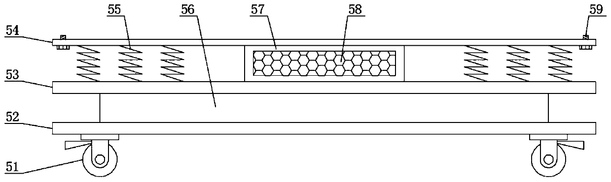
[0031] see Figure 1-Figure 3 , on the basis of Embodiment 1, in order to make the shock absorption effect of the decoration material cutting machine better, in this implementation, preferably, a shock absorption mechanism 5 is arranged below the support base plate 6, and the shock absorption mechanism 5 includes a third support plate 53, a fourth support plate 54 is arranged on the top of the third support plate 53, and the fourth support plate 54 is fixed on the support base plate 6 through the screws 59 at both ends of the lower surface. The connection between the third support plate 53 and the fourth support plate 54 A shock-absorbing plate 57 is provided, and the shock-absorbing plate 57 converts the received kinetic energy into its own elastic potential energy, thereby playing a shock-absorbing role;

[0032] In order to make the cost of the shock absorbing plate 57 lower, in this implementation, preferably, the material of the shock absorbing plate 57 is rubber, and the...


PUM


Abstract

The invention discloses a decoration material cutting machine, and belongs to the technical field of construction machinery. The decoration material cutting machine comprises a supporting bottom plate, a supporting top plate is arranged above the supporting bottom plate, a support is arranged at the joint between the supporting bottom plate and the supporting top plate, a hydraulic cylinder is arranged in the middle of the supporting top plate in a penetrating mode, a first supporting plate is arranged below the hydraulic cylinder, a dust cover is arranged at the joint between the first supporting plate and the hydraulic cylinder, a driving motor is arranged at one end of the upper surface of the first supporting plate, and a cutter is arranged at the output end of the driving motor. A dust removal mechanism is arranged on the decoration material cutting machine, and dust generated during working of the cutting machine can be collected by a dust removal box on the dust removal mechanism; and secondly, limiting plates on the two sides of the dust removal box are matched with baffles to be used, so that a closed space is formed in the cutting area, a large amount of dust is preventedfrom flying out of the decoration material cutting machine during working, the dust is prevented from scattering all around, and the influence on the use experience of a user on the decoration material cutting machine is avoided.

Description

technical field [0001] The invention belongs to the technical field of construction machinery, and in particular relates to a decoration material cutting machine. Background technique [0002] Cutting machines are divided into flame cutting machines, plasma cutting machines, laser cutting machines and water cutting machines. The laser cutting machine has the fastest efficiency, the highest cutting precision, and the cutting thickness is generally small. The cutting speed of the plasma cutting machine is also very fast, and the cutting surface has a certain slope. [0003] Chinese patent (publication number is CN206999159U) discloses a material cutting machine for decoration, including a base, a support plate, a chute, a spiral support, a first splint, a spiral rod, a spiral handle, a machine box, a cutting disc, and a handle , a cross arm, a noise absorber, a vacuum cleaner and a second splint, the base is fixedly connected to the support plate, the upper surface of the ba...

Claims


Application Information

Patent Timeline
Patent Type & Authority Applications(China)
IPC IPC(8): B23D19/00B23D33/00B23Q11/08
CPCB23D19/00B23D33/00B23Q11/08
Inventor 王亢
Owner 王亢
Why Eureka
Try Eureka