
Rotary worktable for assembling piston rod of gas spring

A technology of rotary table and piston rod, which is applied in the direction of assembly machines, manufacturing tools, metal processing equipment, etc., and can solve the problems of gas spring performance damage, easy wear of the piston rod surface, complex processing, etc.

Inactive Publication Date: 2019-08-02
宁波力品格自动化科技有限公司
View PDF11 Cites 3 Cited by
  • Summary
  • Abstract
  • Description
  • Claims
  • Application Information

AI Technical Summary

Problems solved by technology

Gas springs are used in office furniture, and the piston rod of the gas spring is made of round steel. The surface of the currently used piston rod is electroplated. When the gas spring is working, the piston rod performs stretching or compression movement, and the long-term continuous impact The surface of the piston rod is easy to wear and fatigue, and the life of the piston rod is reduced, and the structure of the combination of the piston rod and the piston is not ideal, and the processing is more complicated, which cannot meet the needs of the product.
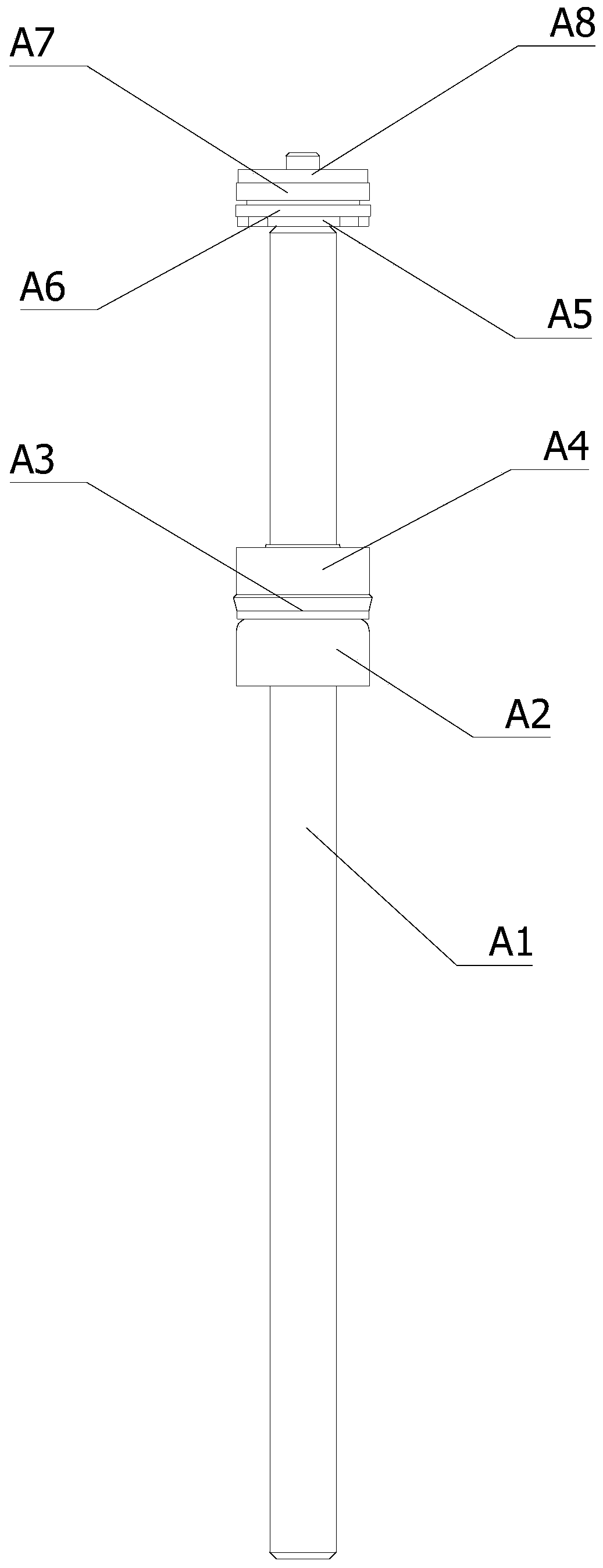
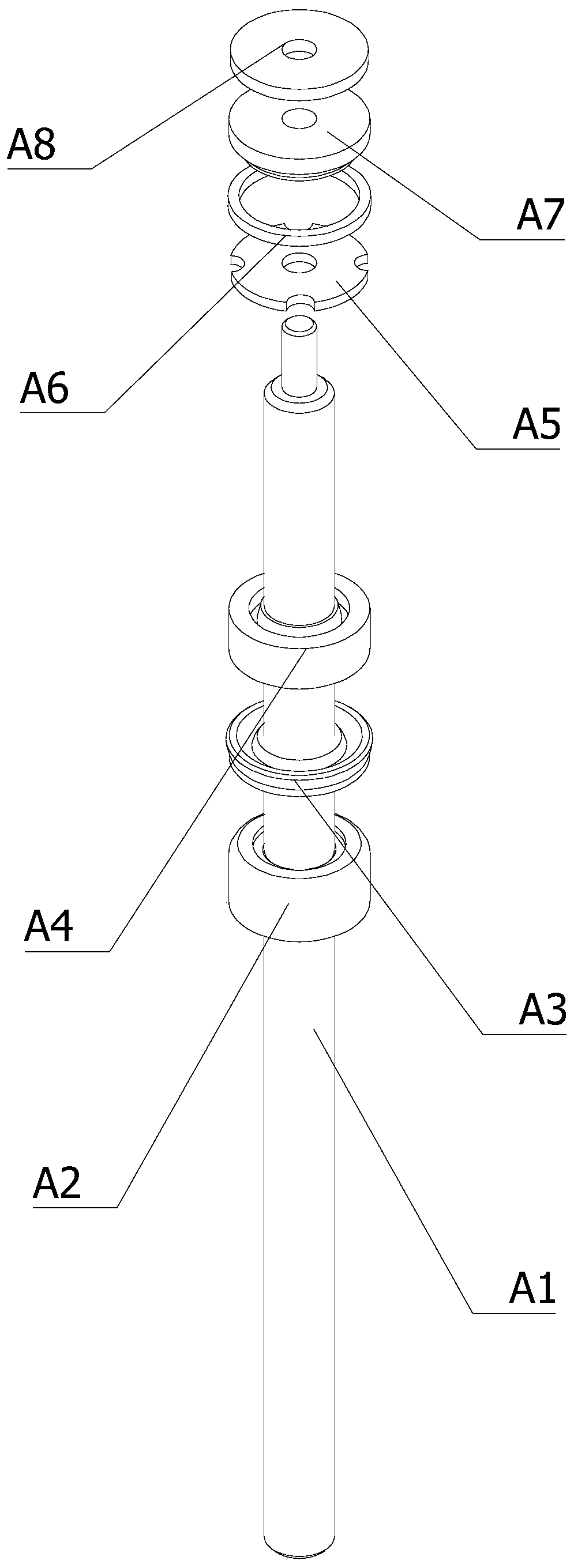
[0004] There are many kinds of sleeves and gaskets installed on the piston rod. The shape and installation sequence of each type of sleeve and gasket are different. Any wrong installation or missing installation will damage the performance of the gas spring; however, workers have to assemble it by hand for a long time There are hidden dangers of errors in the process, and there is currently a lack of an automated assembly system to avoid the above problems

Method used


Image

  • Rotary worktable for assembling piston rod of gas spring
  • Rotary worktable for assembling piston rod of gas spring
  • Rotary worktable for assembling piston rod of gas spring

Examples


Embodiment Construction

[0051] The technical solutions of the present invention will be further described below in conjunction with the accompanying drawings and through specific implementation methods.

[0052] Wherein, the accompanying drawings are only for illustrative purposes, showing only schematic diagrams, rather than physical drawings, and should not be construed as limitations on this patent; in order to better illustrate the embodiments of the present invention, some parts of the accompanying drawings will be omitted, Enlargement or reduction does not represent the size of the actual product; for those skilled in the art, it is understandable that certain known structures and their descriptions in the drawings may be omitted.

[0053] In the drawings of the embodiments of the present invention, the same or similar symbols correspond to the same or similar components; , "inner", "outer" and other indicated orientations or positional relationships are based on the orientations or positional ...


PUM


Abstract

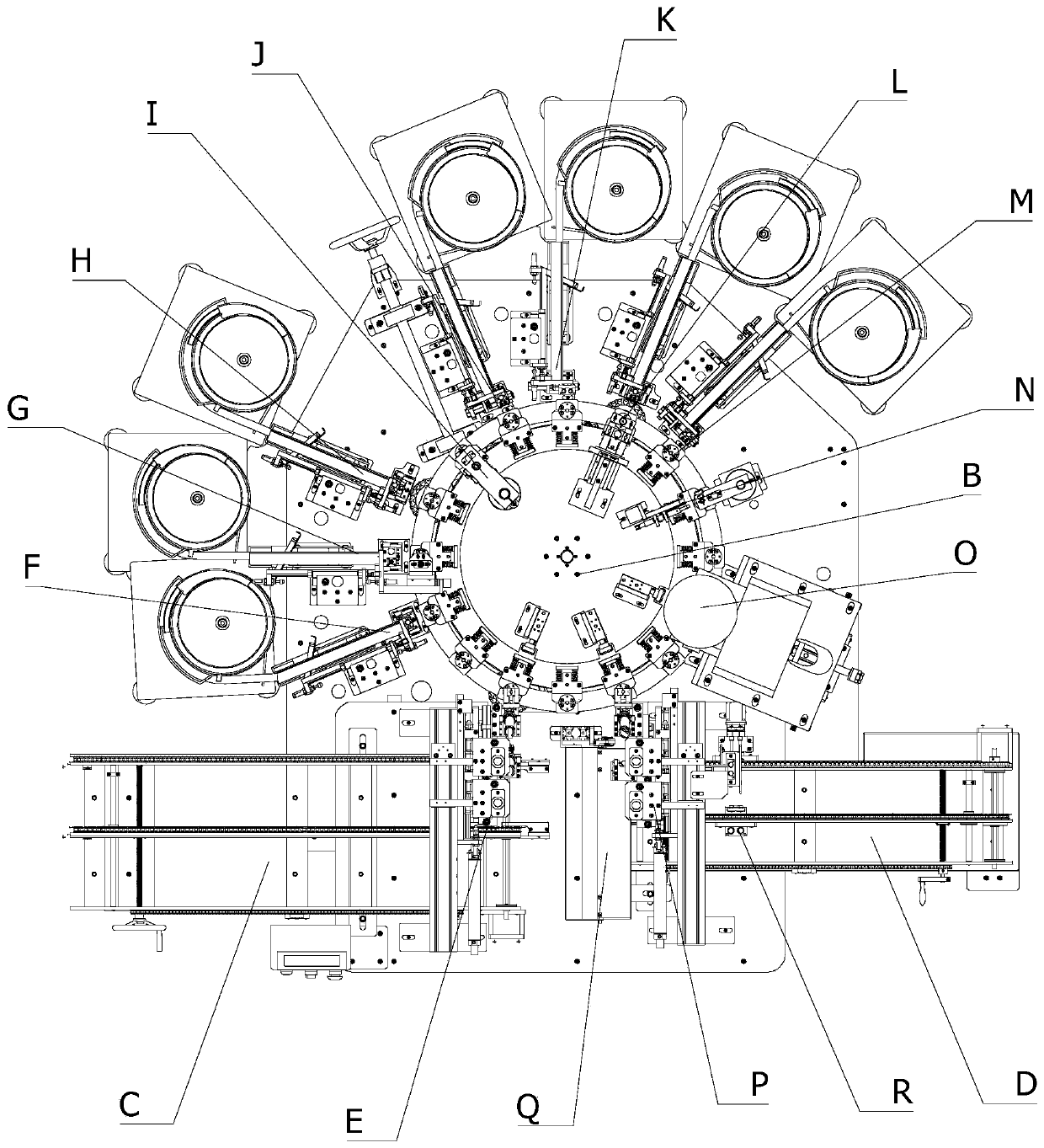
The invention relates to the technical field of piston rod production equipment, in particular to a rotary worktable for assembling a piston rod of a gas spring. The rotary worktable comprises a worktable, and an electric rotating table and a supporting ring lifting mechanism fixedly mounted on the worktable. A rotating shaft of the electric rotating table and the working direction of the supporting ring lifting mechanism are arranged vertically. A piston rod supporting ring is fixedly mounted at the working end of the supporting ring lifting mechanism, the piston ring supporting ring is of aring shape coaxial with the working part of the electric rotating table, a plurality of self-locking fixers distributed uniformly around the axis of the electric rotating table are arranged on the electric rotating table, the fixing parts of the self-locking fixers are fixedly mounted at the edge of the working part of the electric rotating table, the working parts of the self-locking fixers are suspended on the outer side of the working part of the electric rotating table, and the piston rod supporting ring is located right below the working parts of the self-locking fixers. The rotating worktable can fit piston rods of different lengths and can either fix the piston rod or unfix the piston rod automatically.

Description

technical field [0001] The invention relates to the technical field of piston rod production equipment, in particular to a rotary worktable for assembling gas spring piston rods. Background technique [0002] Gas spring is an industrial accessory that can perform functions such as support, buffer, brake, height adjustment and angle adjustment. It consists of the following parts: pressure cylinder, piston rod, piston, sealing guide sleeve, filler (inert gas or oil-gas mixture), in-cylinder control element and out-of-cylinder control element (referring to controllable gas spring) and joints, etc. The principle is to fill the closed pressure cylinder with an inert gas or an oil-gas mixture, so that the pressure in the cavity is several times or dozens of times higher than the atmospheric pressure, and the pressure difference generated by the cross-sectional area of ​​the piston rod is smaller than that of the piston. To realize the movement of the piston rod. [0003] The gas...

Claims


Application Information

Patent Timeline
Patent Type & Authority Applications(China)
IPC IPC(8): B23P21/00
CPCB23P21/006
Inventor 王旭东胡威明魏海泉
Owner 宁波力品格自动化科技有限公司
Learn More