A thermo-induced phase change thermal control skin based on near-field thermal radiation and its application in spacecraft

A thermally induced phase change and thermal radiation technology, applied in sputtering coating, metal material coating process, vacuum evaporation coating, etc., can solve thermally induced phase change material deposition, performance degradation, small emissivity adjustment range problem, to achieve the effect of no moving parts

Active Publication Date: 2021-10-29
HARBIN INST OF TECH
View PDF2 Cites 0 Cited by
  • Summary
  • Abstract
  • Description
  • Claims
  • Application Information

AI Technical Summary

Problems solved by technology

[0004] However, the reported thermal phase change thermal control technology has one or more problems as follows: (1) The thermal phase change material is deposited on the outermost layer of the device
At this time, when the thermally induced phase change material is directly exposed to outer space, the complex space environment such as atomic oxygen and proton electron radiation will cause its performance to degrade, thereby weakening the thermal control effect of the device and even failing.
(2) The emissivity adjustment mechanism of thermal phase change materials is far-field radiation heat transfer, the emissivity adjustment range is small (less than 0.3), and the emissivity change temperature range is too wide (greater than 100K)

Method used


Image

  • A thermo-induced phase change thermal control skin based on near-field thermal radiation and its application in spacecraft
  • A thermo-induced phase change thermal control skin based on near-field thermal radiation and its application in spacecraft
  • A thermo-induced phase change thermal control skin based on near-field thermal radiation and its application in spacecraft

Examples


Embodiment 1

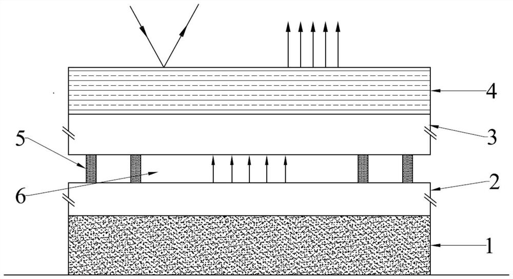
[0058] A kind of heat-induced phase change thermal control skin, including base 1, inner layer film system 2, outer layer film system 3 and optical solar reflector 4 from bottom to top, and between inner layer film system 2 and outer layer film system 3 has The spacer 5, the spacer 5 forms a vacuum gap 6 with a pitch of micronano scale between the inner layer film system 2 and the outer layer film system 3, and the inner layer film system 2 contains a thermally induced phase change Thermally induced phase change film layer composed of materials.

[0059] Specifically, the material of substrate 1 is SiO 2 , the inner film system 2 is single-layer VO 2 The thin film, with a film thickness of 200nm, is coated by magnetron sputtering. The CMO-based OSR produced by the British Point-source company is selected as the optical solar reflector 4, its infrared emissivity ε = 0.87, and the solar spectral absorptivity α s =0.085, the outermost layer of the selected optical solar reflec...

Embodiment 2

[0062] A kind of heat-induced phase change thermal control skin, including base 1, inner layer film system 2, outer layer film system 3 and optical solar reflector 4 from bottom to top, and between inner layer film system 2 and outer layer film system 3 has The spacer 5, the spacer 5 forms a vacuum gap 6 with a pitch of micronano scale between the inner layer film system 2 and the outer layer film system 3, and the inner layer film system 2 contains a thermally induced phase change Thermally induced phase change film layer composed of materials.

[0063] Specifically, the material of substrate 1 is SiO 2 , the inner film system 2 is single-layer VO 2 Thin film, with a film thickness of 100nm, is coated by magnetron sputtering. The CMO-based OSR produced by the British Point-source company is selected as the optical solar reflector 4, its infrared emissivity ε = 0.87, and the solar spectral absorptivity α s = 0.085. Plating a layer of silver (Ag) base film and a layer of in...

Embodiment 3

[0066] A kind of heat-induced phase change thermal control skin, including base 1, inner layer film system 2, outer layer film system 3 and optical solar reflector 4 from bottom to top, and between inner layer film system 2 and outer layer film system 3 has The spacer 5, the spacer 5 forms a vacuum gap 6 with a pitch of micronano scale between the inner layer film system 2 and the outer layer film system 3, and the inner layer film system 2 contains a thermally induced phase change Thermally induced phase change film layer composed of materials.

[0067] Specifically, the material of the substrate 1 is SiC, and the inner film system 2 includes an inner layer of VO 2 film and an outer layer of SiC film, where VO 2 The film thickness of the film is 100 nm, the film thickness of the SiC film is 20 nm, and the film is deposited by magnetron sputtering. The CMO-based OSR produced by the British Point-source company is selected as the optical solar reflector 4, its infrared emissi...


PUM

PropertyMeasurementUnit
thicknessaaaaaaaaaa
thicknessaaaaaaaaaa
thicknessaaaaaaaaaa

Abstract

The invention relates to a heat-induced phase change thermal control skin based on near-field thermal radiation and its application in spacecraft. The heat-induced phase change thermal control skin includes a base, an inner layer film system, an outer layer film system and a protective layer from bottom to top, and there is a spacer between the inner layer film system and the outer layer film system, and the spacer makes the inner film system A vacuum gap with a pitch of micronano scale is formed between the layer film system and the outer layer film system; and the inner layer film system includes a thermally induced phase change film layer composed of a thermally induced phase change material; the protective layer has High IR emissivity or both high IR emissivity and low solar spectrum absorptivity. On the one hand, this thermo-induced phase change thermal control skin has good adaptability to the space environment, which solves the problem of performance degradation of phase change materials caused by direct exposure to the space environment; on the other hand, it can provide a large emission within a narrow temperature range. Rate adjustment range, can be applied in spacecraft.

Description

technical field [0001] The invention relates to the technical field of thermal control devices, in particular to a thermal phase change thermal control skin based on near-field thermal radiation and its application in spacecraft. Background technique [0002] Spacecraft will face complex and changeable space thermal environment during its orbital operation, and its thermal environment will change drastically with the difference of thermal boundary conditions and internal thermal state. Effective thermal control of the spacecraft to keep it in an appropriate temperature range under any working conditions is a key factor to ensure the normal, continuous and reliable operation of the spacecraft. [0003] Among various thermal control technologies, thermal phase change thermal control utilizes the characteristics of optical properties of thermal phase change materials that change with temperature to intelligently and autonomously adjust the emissivity of thermal control devices ...

Claims


Application Information

Patent Timeline
Patent Type & Authority Patents(China)
IPC IPC(8): C23C14/35C23C14/08C23C14/10C23C14/06
CPCC23C14/0635C23C14/083C23C14/086C23C14/10C23C14/35
Inventor 赵军明徐德宇裘俊
Owner HARBIN INST OF TECH
Why Eureka
Try Eureka