Novel grout supplementing method and device for micro pile

A micropile and grout filling technology, which is applied to sheet pile walls, buildings, and foundation structure engineering, can solve problems such as grouting misunderstandings, affecting grouting quality, and slow grouting process, so as to prevent grout from flowing back and ensure grouting Effect, the effect of evenly filling the slurry

Inactive Publication Date: 2019-08-02
中隧隧盾国际建设工程有限公司
View PDF6 Cites 1 Cited by
  • Summary
  • Abstract
  • Description
  • Claims
  • Application Information

AI Technical Summary

Problems solved by technology

[0004] 1) Firstly, the length of the grout filling pipe itself is relatively long. During the flow of the grout, the wall of the grout replenishment pipe will produce resistance to the grout, so that the flow rate of the injected grout will slow down; and when the grout at the end of the grout replenishment pipe is full, The grout will flow back, which will cause further resistance to the injected grout. When the confluent grout passes through the grouting hole, it cannot rely on the pressure of the grouting pump to enter the grouting port, and can only overflow to the wall and the wall through its own gravity. In the gap between the pipe walls, the injection process of the grout is slow, and at the same time, the uniformity of the grouting at each position of the grouting pipe is poor, which affects the quality of the grouting
[0005] 2) At the same time, according to the opening characteristics of the grouting hole of the grouting pipe itself, the grouting hole is located around and at the end of the pipe wall. When grouting, when the grout flows out of the bridge gap, it proves that the grout in the gap has been filled , and in the process of grouting, since the grouting holes are evenly distributed around the wall of the grouting pipe along the axis, when grouting, the grout injected into the grouting hole at the front end will flow out from the gap of the bridge in advance, so that People mistakenly think that the gap has been filled and stop grouting, but in fact the gap has not been filled, resulting in misunderstanding of grouting, resulting in incomplete grouting and affecting the quality of grouting
[0006] 3) The current grouting technology (using a pressure pump to inject grout into the pre-buried grouting pipe, without an auxiliary grouting device) is relatively simple, with poor functionality, the flow rate of the grout at the grouting end is unstable, and the grouting effect is poor

Method used


Image

  • Novel grout supplementing method and device for micro pile
  • Novel grout supplementing method and device for micro pile
  • Novel grout supplementing method and device for micro pile

Examples


Embodiment 1

[0045] Such as Figure 1-4 As shown, the present invention discloses a novel grouting device for micropile, grouting pipe 1, positioning grouting device 2;

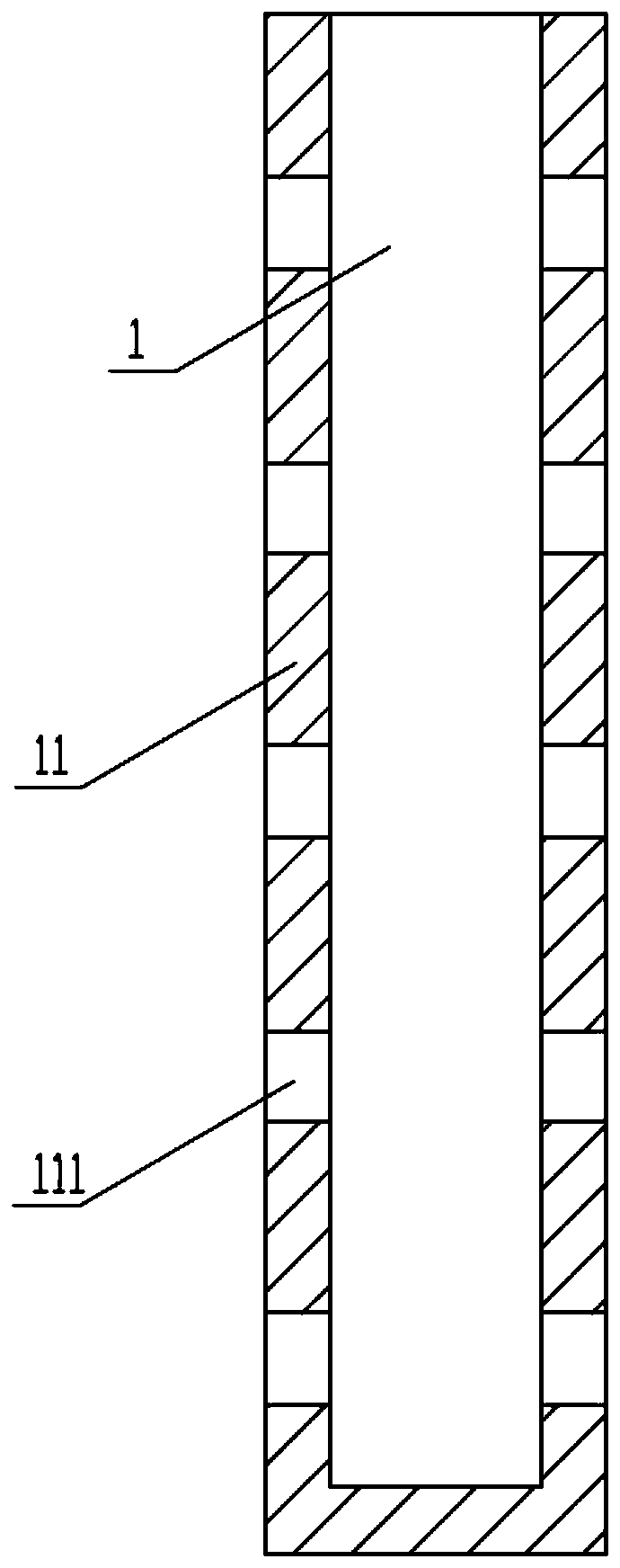
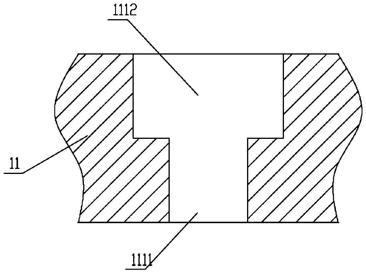
[0046] The grout filling pipe 1 includes a pipe body 11 and a non-return device 12; the pipe body 11 is a hollow pipe with one end open and one end closed, and a grout filling hole 111 is arranged on the side wall of the pipe body 11; the non-return device 12 is set at the grouting hole 111 to ensure that the fluid can only flow outward in one direction from the inside of the pipe body 11;

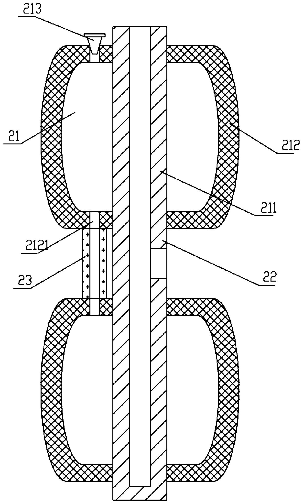
[0047] The positioning grouting device 2 includes a plugging part 21 and a grouting part 22; the grouting part 22 is connected with the plugging part 21 up and down; the plugging part 21 is a hollow jacket structure, including an inner tube 211. Outer jacket 212, a deformable space is formed between the outer jacket 212 and the inner pipe 211, and the outer jacket 212 is provided with a vent 2121; the grout filling part 22 is a commu...


PUM


Abstract

The invention relates to the technical field of micro-pile grout supplementing construction, and in particular to a novel grout supplementing method and device for a micro pile. The method comprises the steps of: 1) pre-burying a grout supplementing pipe in a pouring pile; (2) after the pouring pile is poured and solidified, inserting a positioning grout supplementing device into the grout supplementing pipe pre-buried in the pouring pile, and grouting is conducted; and 3) moving the positioning grout supplementing device, and repeating the step 2) until the grout supplementing is completed. The method has the beneficial effects that only the part with the cavity is supplemented with grout; the periphery of a cap plug is supplemented with grout, and grout supplementation is more uniform; anon-return device is arranged to prevent grout from flowing back, and long-term pressure maintaining is not needed; an expanded polytetrafluoroethylene material is adopted, so that exhaust can be realized; grout supplementing can be positioned, and the grout supplementing part and the grout supplementing amount can be known conveniently; for the part close to the edge, grout can be prevented fromoverflowing under the action of pressure, and the grout supplementing effect is guaranteed.

Description

technical field [0001] The invention relates to the technical field of micropile grouting construction, in particular to a novel grouting method and device for micropile. Background technique [0002] At present, when bridges and tunnels are poured, grouting pipes (a long pipe with through holes on the pipe wall and pipe ends) are often embedded inside. The function of pre-embedded grouting pipes is to use the grouting pipes as bridges On the other hand, after the bridge concrete is poured, the grout can be poured into the grouting pipe through the grouting pump, and the grout will flow through the grouting hole opened on the grouting pipe under the action of pressure. To the gap between the bridge wall and the pipe body caused by the air bubbles in the concrete, so as to fill the gap and improve the compactness of concrete pouring, and then fill the grout filling pipe with grout to improve the pouring quality of the bridge. [0003] Nowadays, there are disadvantages when u...

Claims


Application Information

Patent Timeline
Patent Type & Authority Applications(China)
IPC IPC(8): E02D15/04E02D5/62
CPCE02D5/62E02D15/04
Inventor 邬靓王成刚李成龙邢志国王超刘铁马林超
Owner 中隧隧盾国际建设工程有限公司
Why Eureka
Try Eureka