Visual device detection method and instrument, and application thereof in smart grid

A technology for equipment testing and equipment, applied in the direction of instruments, measuring electricity, measuring electrical variables, etc., can solve problems such as discharge failures, and achieve high cost performance, improved professionalism, and good economy.

Inactive Publication Date: 2019-08-02
STATE GRID BEIJING ELECTRIC POWER +2
View PDF25 Cites 0 Cited by
  • Summary
  • Abstract
  • Description
  • Claims
  • Application Information

AI Technical Summary

Problems solved by technology

[0004] In view of this, the object of the present invention is to provide a visual equipment detection method and instrument and its application in the smart grid, to solve the problem that the damp equipment in the station room cannot detect the equipment failure in a timely and accurate manner, and to solve the discharge failure caused by the equipment damp Accurate judgment

Method used


Image

  • Visual device detection method and instrument, and application thereof in smart grid
  • Visual device detection method and instrument, and application thereof in smart grid
  • Visual device detection method and instrument, and application thereof in smart grid

Examples


Embodiment Construction

[0029] In order to make the purpose, technical solutions and advantages of the embodiments of the present invention clearer, the technical solutions of the present invention will be clearly and completely described below in conjunction with the accompanying drawings. Obviously, the described embodiments are part of the embodiments of the present invention, not all of them. the embodiment. Based on the embodiments of the present invention, all other embodiments obtained by persons of ordinary skill in the art without making creative efforts belong to the protection scope of the present invention.

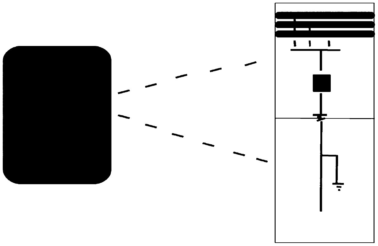
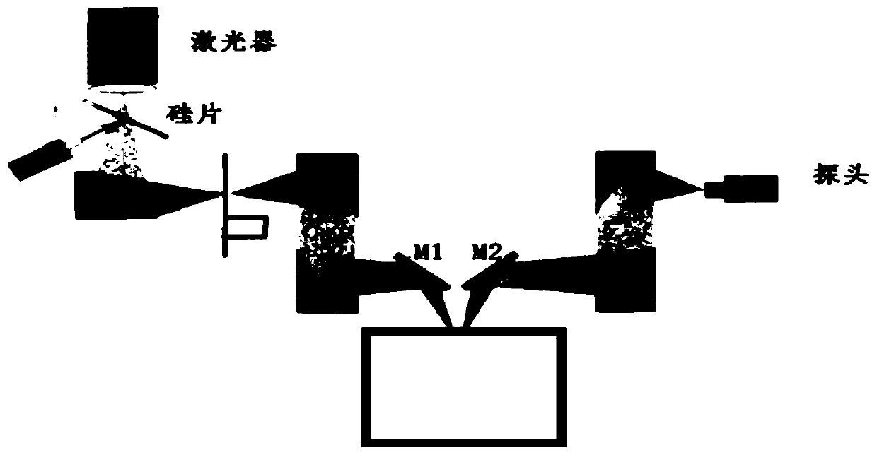
[0030] Such as figure 1 and figure 2 As shown, the visualization device detection method of the present invention realizes the wavelength tuning of the pulse by adjusting the polarization controller, and adopts the optical fiber phase array method to control and obtain the pulse, and controls the laser and the electric scanning mirror synchronously through the computer; The surfac...


PUM


Abstract

The invention discloses a visual device detection method and instrument, and an application thereof in a smart grid. Wavelength tuning of a pulse is realized by adjusting a polarization controller, the obtained pulse is controlled by using an optical fiber phase array method, laser and an electric scanning mirror are synchronously controlled by a computer; then the surface of a detected device isscanned in a grid shape through a laser beam, recorded waveform data are displayed, a fault point and a discharge site in the device can be visually observed, whether the device is faulty is judged onsite, and maintenance and fault repair are performed in time, the problem that the existing detection instrument fails to perform onsite judgment in the fault detection is solved, the delay of the repair time of the device fault is avoided, and the situation of causing serious damage to the device is avoided.

Description

technical field [0001] The invention belongs to the technical field of electric equipment testing instruments, and in particular relates to a visual equipment testing method and instrument and their application in smart grids. Background technique [0002] The company has 145 opening and closing stations, among which there are more than 1,000 station rooms in the community. Every year, the internal discharge phenomenon of the equipment in the station room is relatively prominent due to various reasons, and the number of damaged station rooms reaches 2 to 3. It is caused by complicated reasons. It is inevitable that the equipment in the station room will be damp. Due to the geographical location of the company, there are many open and close stations and underground station rooms. The space of the underground station room is limited, and normal ventilation cannot be carried out. The insulation reduction of long-term damp equipment also causes discharge failures. the main reaso...

Claims


Application Information

Patent Timeline
Patent Type & Authority Applications(China)
IPC IPC(8): G01R31/12
CPCG01R31/1218G01R31/1227
Inventor 王会闯卢宏宇张金金王广林郑永奇李宁吴大伟李彬王军刘迅王程付丽娜王波高冬梅高丽敏南慧李文胜杨越王建勇刘爽李欣阳王兴越王宏威
Owner STATE GRID BEIJING ELECTRIC POWER
Why Eureka
Try Eureka