Pressure relief system and container, building, enclosure or cubicle including pressure relief system

A release system, building technology, applied in the setting of switchgear, switchgear, electrical components, etc., can solve problems such as time delay, and achieve the effects of saving time and cost, avoiding damage, and saving materials

Pending Publication Date: 2021-04-13
ABB (SCHWEIZ) AG
View PDF2 Cites 0 Cited by
  • Summary
  • Abstract
  • Description
  • Claims
  • Application Information

AI Technical Summary

Problems solved by technology

Therefore, known techniques include a significant time delay for the opening of the flap and the pressure may still reach critical levels within the vessel, building, enclosure or compartment

Method used


Image

  • Pressure relief system and container, building, enclosure or cubicle including pressure relief system
  • Pressure relief system and container, building, enclosure or cubicle including pressure relief system
  • Pressure relief system and container, building, enclosure or cubicle including pressure relief system

Examples


Embodiment Construction

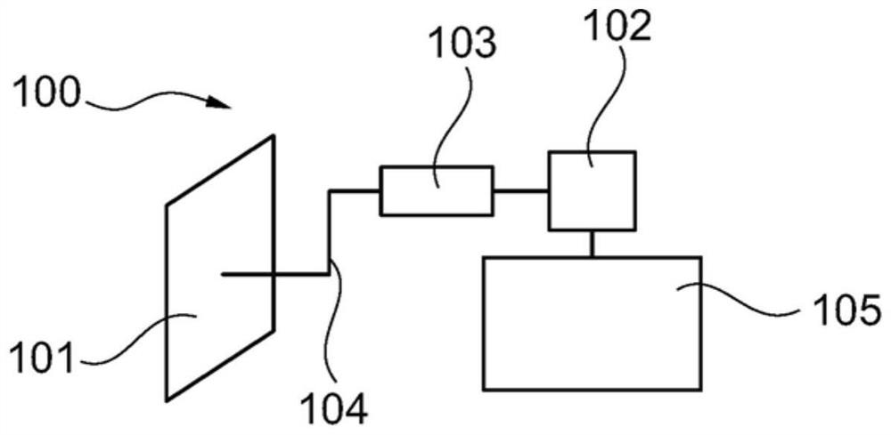
[0021] According to embodiments described herein, an actively actuated pressure relief system is provided that is particularly useful in containers, buildings, enclosures, and compartments with electrical devices. For example, actively driven pressure relief systems can be used in power systems, grids, in installed products, in semiconductor applications, with power converters, switchgear, circuit breakers, motors and generators, and in other used in industrial applications. In general, actively driven pressure relief systems as described herein can be used with high power rectifiers and high current rectifiers.

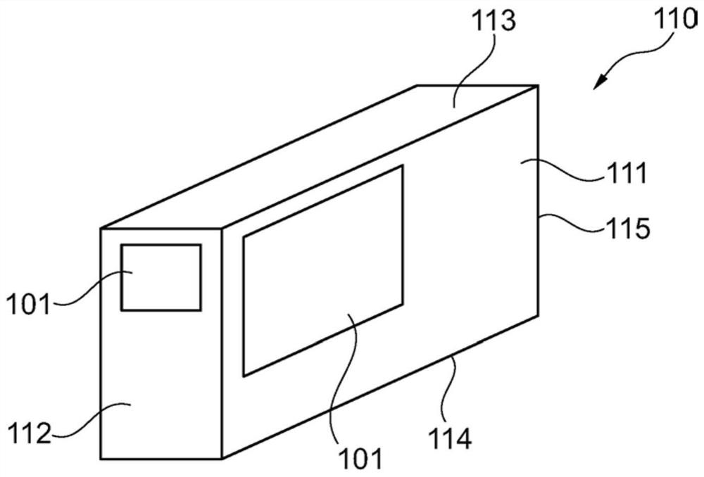
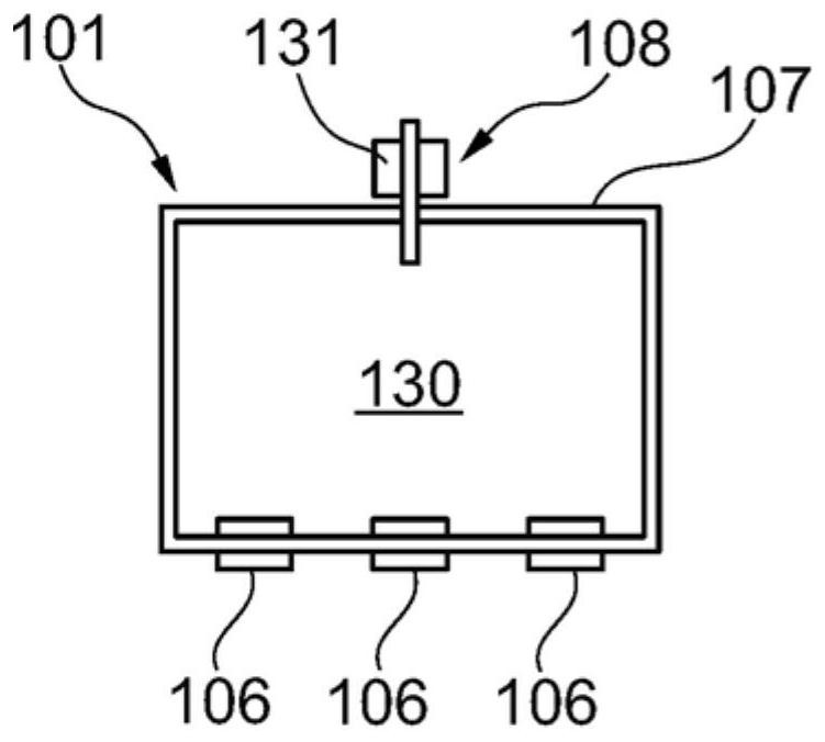
[0022] figure 1 A schematic diagram of an actively actuated pressure relief system 100 and panel 101 according to embodiments described herein is shown. Such as figure 1 The actively driven pressure relief system 100 shown has a fault detection device 102 , in particular an arc fault detection device, and a trigger unit 103 . In some embodiments, the actively ope...


PUM


Abstract

It is proposed an actively driven pressure relief system (100) for a container, a building, an enclosure, or a cubicle (110) with an electrical installation (105). The actively driven pressure relief system includes a panel and further includes a fault detection device (102) for detecting an arc fault in the electrical installation of the container, the building, the enclosure or the cubicle; and a triggering unit (103) for triggering an opening signal for the panel upon detection of an arc fault by the fault detection device. A panel opening mechanism opens the panel in a destructive manner. Further, the container, building, enclosure or cubicle with the actively operated pressure relief system is described. A method for relieving pressure from the container with the panel and an electrical installation inside the container is also described.

Description

technical field [0001] The present invention relates to the field of pressure relief panels, such as pressure relief panels in containers, buildings, enclosures and compartments with electrical devices inside. In particular, the invention relates to pressure relief panels that respond to overpressure in a container, building, enclosure or compartment, caused by an electrical fault. The invention further relates to a method for relieving pressure from a container, building, enclosure or compartment having an electrical installation, in particular for relieving pressure from a container, building, enclosure or compartment through a panel in the event of an electrical failure. Background technique [0002] Special protection of containers, buildings, enclosures and compartments (which may also be collectively referred to as enclosures) with electrical installations inside them against damage, especially caused by electrical faults such as arc faults. Arc faults in electrical i...

Claims


Application Information

Patent Timeline
Patent Type & Authority Applications(China)
IPC IPC(8): H02B13/025
CPCH02B13/025H02H7/125
Inventor 克里特·佩斯雷托·斯塔德勒
Owner ABB (SCHWEIZ) AG
Why Eureka
Try Eureka