Diagnosis support apparatus, diagnosis support method, diagnosis method, and repair method of vacuum degassing tank

a technology of vacuum degassing tank and support apparatus, which is applied in the direction of instruments, manufacturing converters, furniture, etc., can solve the problems of reducing affecting the quality of molten steel, and the iron shell that covers the immersion tubes b, /b>103/b> may become red-hot and be damaged, so as to shorten the time necessary for measurement, avoid refractory troubles, and diagnose the properties quickly and accurately

Active Publication Date: 2020-09-01
NIPPON STEEL CORP
View PDF13 Cites 0 Cited by
  • Summary
  • Abstract
  • Description
  • Claims
  • Application Information

AI Technical Summary

Benefits of technology

[0032]According to the diagnosis support apparatuses of a vacuum degassing tank according to (1) to (13), the camera captures an image of the inner circumferential surface of the immersion tube seen from below at an angle in a state of being disposed outside the inner circumferential surface of the immersion tube in the plan view, and thus a molten substance does not collide with the camera during image capture even in a harsh image capturing environment in which the molten substance drips from the immersion tube immediately after vacuum degassing. Therefore, it is possible to rapidly and accurately diagnose the properties of the inner circumferential surface of the immersion tube immediately after vacuum degassing. In addition, measurement is possible immediately after the end of vacuum degassing, and thus it is possible to shorten the time necessary for measurement. Therefore, it is possible to realize the avoidance of refractory troubles, the maintenance of the qualities of the molten steel, and the extension of the service life of the vacuum degassing tank without stopping the continuous operations of the vacuum degassing tank, and it becomes possible to increase the efficiency of vacuum degassing.
[0033]According to the diagnosis support method of a vacuum degassing tank according to (14) and a diagnosis method of a vacuum degassing tank according to (15), it is possible to rapidly and accurately diagnose or support the diagnosis of the properties of the inner circumferential surface of the immersion tube immediately after vacuum degassing using the diagnosis support apparatus according to (1) to (13). In addition, measurement is possible immediately after the end of vacuum degassing, and thus it is possible to shorten the time necessary for measurement. Therefore, it is possible to realize the avoidance of refractory troubles, the maintenance of the qualities of the molten steel, and the extension of the service life of the vacuum degassing tank without stopping the continuous operations of the vacuum degassing tank, and it becomes possible to increase the efficiency of vacuum degassing.
[0034]According to the repair method of a vacuum degassing tank according to (16), the inner circumferential surface of the immersion tube is repaired using an optimal repair method determined in the repair technique determination step according to (15), and thus it is possible to avoid consuming the repair time more than necessary. Therefore, it is possible to increase the efficiency of vacuum degassing.

Problems solved by technology

In addition, there is a concern that an iron shell that covers the immersion tubes 104 and the lower portion tank 103 may become red-hot and be damaged.
In summary, cracks in the lining refractory α cause the degradation of the quality of the molten steel and the shortening of the service life of the degassing tank and act as a cause for inhibiting the manufacturing of clean steel.
In addition, in the case of cooling the lining refractory α in order for the diagnosis, there is a concern that the lining refractory α may be damaged due to the cooling.
However, in a case where the camera for observing the inside of the furnace is inserted into the immersion tube in a high-temperature state immediately after an RH process using the technique disclosed by Patent Document 1, there is a concern that molten substances (for example, a slag and a scull) remaining in the RH degassing tank may drip from the immersion tube and the camera may be broken.
In this case, it is not possible to carry out accurate diagnoses.
In this case, it is difficult to carry out accurate diagnoses.
When it is not possible to carry out an accurate diagnosis, not only is the necessity of a repair misjudged, but the selection of a repair method is also misjudged.
As a result, there is a concern that the refractory troubles may be caused and the degradation of the qualities of molten steel (for example, the infiltration of inclusions derived from a refractory into the molten steel) and the shortening of the service lives of vacuum degassing tanks may be caused.
In addition, there are cases where the continuous operations of vacuum degassing tanks are stopped and thus, conversely, an excess repair cost may be incurred.

Method used


Image

  • Diagnosis support apparatus, diagnosis support method, diagnosis method, and repair method of vacuum degassing tank
  • Diagnosis support apparatus, diagnosis support method, diagnosis method, and repair method of vacuum degassing tank
  • Diagnosis support apparatus, diagnosis support method, diagnosis method, and repair method of vacuum degassing tank

Examples


first embodiment

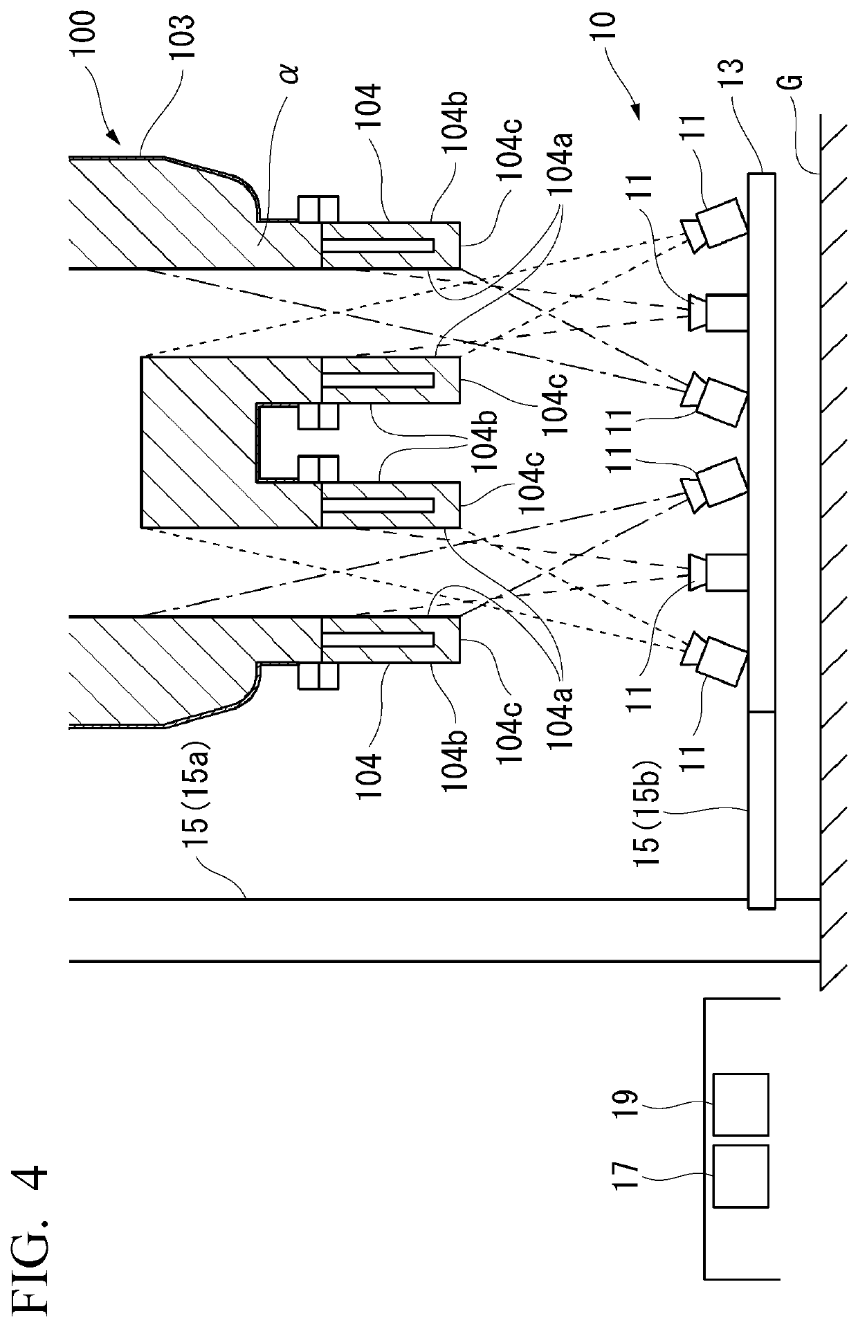
[0055]FIG. 4 is a schematic front view showing a vacuum degassing tank diagnosis support apparatus 10 (hereinafter, simply referred to as “the diagnosis support apparatus 10”) and an RH degassing tank 100, which is a diagnosis subject, according to a first embodiment of the present invention. In addition, FIG. 5 is a schematic plan view showing a positional relationship between the diagnosis support apparatus 10 and the RH degassing tank 100 at the time of image capture.

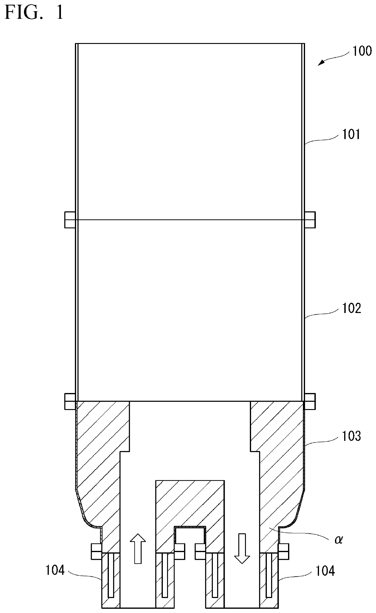
[0056]As shown in FIG. 4, the diagnosis support apparatus 10 diagnoses, as a subject, the lining refractories α provided on inner circumferential surfaces 104a of two immersion tubes 104 in the RH degassing tank 100 described with reference to FIG. 1. The diagnosis support apparatus 10 supports diagnoses by image capturing the inner circumferential surfaces 104a of the immersion tubes 104 using a plurality of cameras 11 disposed at an angle below the respective immersion tubes 104, acquiring the images as data, and i...

second embodiment

[0103]Hereinafter, an RH degassing tank diagnosis support method according to a second embodiment of the present invention (hereinafter, simply referred to as “the diagnosis support method”) will be described.

[0104]In the diagnosis support method according to the present embodiment, in a flowchart shown in FIG. 9, a image capturing step S1 and an image-processing step S2 are sequentially carried out. These steps S1 and S2 are carried out in a period of time between the completion of the previous charge of RH degassing and the beginning of the following charge of RH degassing.

[0105]First, in the image capturing step S1, after the end of RH degassing, for example, the inner circumferential surfaces 104a of the immersion tubes 104 are image captured using the cameras 11 in the diagnosis support apparatus 10 according to the first embodiment.

[0106]Specifically, the cameras 11 image capture the immersion tubes 104 in a high-temperature state immediately after RH degassing in a state of b...

third embodiment

[0109]Hereinafter, an RH degassing tank diagnosis method according to a third embodiment of the present invention (hereinafter, simply referred to as “the diagnosis method”) will be described.

[0110]In the diagnosis method according to the present embodiment, in the flowchart shown in FIG. 9, the image capturing step S1, the image-processing step S2, a crack specification step S3, and a repair technique determination step S4 are sequentially carried out. These steps S1 to S4 are carried out in a period of time between the completion of the previous charge of RH degassing and the beginning of the following charge of RH degassing.

[0111]First, in the image capturing step S1, after the end of RH degassing, for example, the inner circumferential surfaces 104a of the immersion tubes 104 are image captured using the cameras 11 in the diagnosis support apparatus 10 according to the first embodiment.

[0112]Specifically, the cameras 11 image capture the immersion tubes 104 in a high-temperature...


PUM

PropertyMeasurementUnit
exposure timeaaaaaaaaaa
lengthsaaaaaaaaaa
lengthaaaaaaaaaa

Abstract

This diagnosis support apparatus is a diagnosis support apparatus of a vacuum degassing tank having an immersion tube that extends downward, the diagnosis support apparatus including a camera that is configured to capture an image of an inner circumferential surface of an immersion tube seen from below at an angle in a state of being disposed outside the inner circumferential surface of the immersion tube in a plan view and acquire the image as data and an image processor that is configured to be connected to the camera and carry out image-processing of the data.

Description

TECHNICAL FIELD OF THE INVENTION[0001]The present invention relates to a diagnosis support apparatus, a diagnosis support method, a diagnosis method, and a repair method of a vacuum degassing tank.[0002]Priority is claimed on Japanese Patent Application No. 2017-035438, filed Feb. 27, 2017, the content of which is incorporated herein by reference.RELATED ART[0003]In a series of refining steps for manufacturing clean steel, in many cases, vacuum degassing by an RH method or a DH method (RH process or DH process) is carried out on molten steel. In vacuum degassing, vacuum degassing tanks (RH degassing tanks or DH degassing tanks) are used.[0004]FIG. 1 shows a cross-sectional view of an RH degassing tank 100 as an example of the vacuum degassing tanks. The RH degassing tank 100 includes an upper portion tank 101, a middle portion tank 102, a lower portion tank 103, and two immersion tubes 104 sequentially from top to bottom. The two immersion tubes 104 respectively extend downward from...

Claims


Application Information

Patent Timeline
Patent Type & Authority Patents(United States)
IPC IPC(8): G01N21/954G01B11/30F27D21/02G01N21/88
CPCG01B11/30F27D21/02G01N21/954G01N2201/021G01N2021/8845C21C7/10F27D21/00G01N25/72C21C5/4673F27D21/0021C21B2300/04
Inventor KUDO, SUSUMUNITTA, MICHIOMIYASHITA, MASAKIFUJITA, SEIYAWATABE, NAOKI
Owner NIPPON STEEL CORP
Why Eureka
Try Eureka