Inkjet printing apparatus and ink printing method

a printing apparatus and inkjet technology, applied in the direction of printing, other printing apparatus, etc., can solve the problems of prolonged drying time or fixing time of ink ejected on the printing sheet, affecting the compatibility of high speed printing and high image quality, and lowering the quality of color images, etc., to achieve prolonging the fixing time, increasing the solidity of the printing image, and increasing the image quality

Active Publication Date: 2006-06-13
CANON KK
View PDF24 Cites 3 Cited by
  • Summary
  • Abstract
  • Description
  • Claims
  • Application Information

AI Technical Summary

Benefits of technology

[0017]The present invention is made based on finding the new idea that the distribution of the reacting liquid especially inside the printing sheet is made even when applying smaller amount of the reacting liquid than the amount that can be absorbed by the printing sheet, and provides an inkjet printing apparatus and an ink jet printing method that can form an image with color ink at desired density and improve a fixing efficiency.
[0018]Further, the present invention solves a problem that caused by a condition of fibers in a printing sheet, in consideration of a conventional suction system which can not perform an even air suction for the printing sheet having the condition of fibers, and the object of the present invention is to provide an ink jet printing apparatus and an ink jet printing method which prevent a fixing time being lengthened, decrease in print quality due to an image being rubbed, and fluctuation in a print density.
[0031]As a result, the reacting between the ink and the reacting liquid can be promoted and become effective. Further, in the inkjet printing apparatus, when the printing is conducted by generating the reacting by which the penetration of the ink solvent is delayed on the printing sheet, it becomes possible to prevent that the fixing time is prolonged thereby.
[0032]Further, by the even diffusion of the reacting liquid by the suction, not only a case where the fixing of the reactive of the ink is stayed on the printing sheet surface, a case to make uniformly fixed in the vicinity of the printing sheet surface, becomes possible, and the increase of the solidity of the printing image and the increase of the image quality by the uniformity of the printing image are obtained.
[0033]It should be noted that embodiments of the present invention stated later dose not especially describe suction forces and structures for suction. However, for the present invention which can use a function of a suction device at a maximum, the ordinary person in the art can easily determine the suction force or the like with use of known devices. In the embodiments of the present invention, suction openings, distribution of the suction openings and the suction force are determined on the level in which normal printing sheets can be stably fed while the printing sheet is subjected to the suction.

Problems solved by technology

Further, in the case that a color image is printed, the bleeding by a fact in which the ink is mixed in the boundary portion between different colors, is caused, and becomes a cause by which the quality of the color image is lowered.
These phenomena are conspicuously caused in the case where the high speed printing is conducted, because the permeability of the ink constitutes a cause of the phenomenon, and therefore, the compatibility of the high speed printing and the high image quality is made difficult.
As the result, there is a problem that the drying time or fixing time of the ink ejected on the printing sheet is prolonged.
Then, the rubbed and damaged amount is relatively increased.
Further, since many of the insolubilized matter or the like stay on the surface of the printing sheet, there are many cases where a film formed with stayed insolubilized matter or the like becomes un-uniform, and as the result, there is, sometimes, also a case where the fluctuation of density is generated in the printed image.
The inventors of this application have found out that the cause of the fluctuation of density is that much of the reacting liquid remains on the surface of the printing sheet, and is uneven distribution of the reacting liquid which is controlled by a condition of fibers in the printing sheet.
Further, as a result, the application of the coloring material is fluctuated according to the fluctuated distribution of the reacting liquid and thus unevenness in fixing the coloring material is caused.
For this reason, the print density distribution becomes what is far removed from a desired distribution, and thus the print quality becomes degraded.
On the other hand, in the case of applying great amount reacting liquid, the opposite effect that an image is formed only on the surface of the printing sheet may be caused and thus an image quality is noticeably degraded.

Method used


Image

  • Inkjet printing apparatus and ink printing method
  • Inkjet printing apparatus and ink printing method
  • Inkjet printing apparatus and ink printing method

Examples


embodiment 1

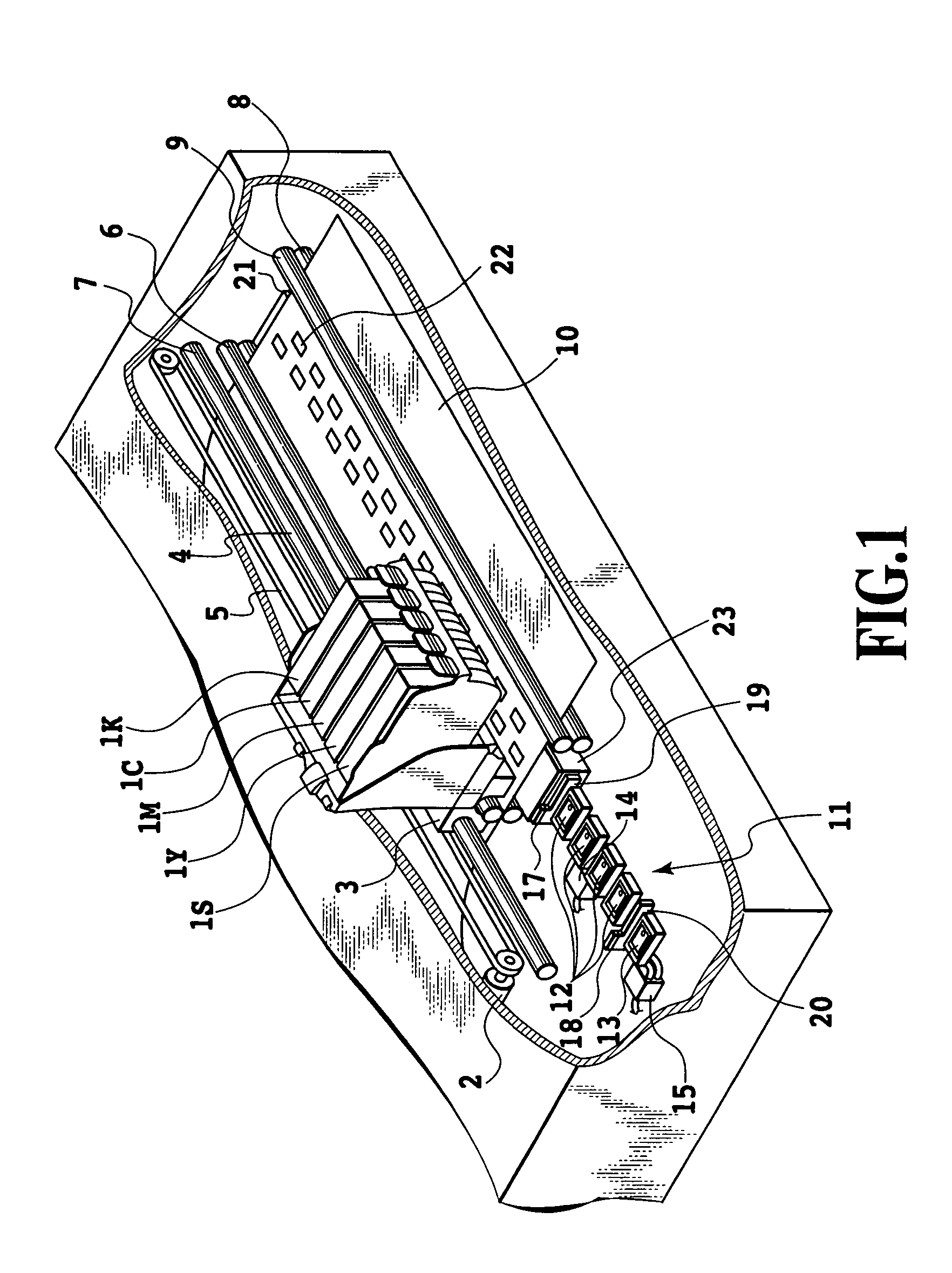
[0049]FIG. 1 is a perspective view showing an outline structure of an inkjet printer, according to an embodiment of an inkjet printing apparatus of the present invention, and FIGS. 2A, 2B and FIG. 3 are views for describing in detail the structure of the printing head used in this printer. Initially, this printing head will be described.

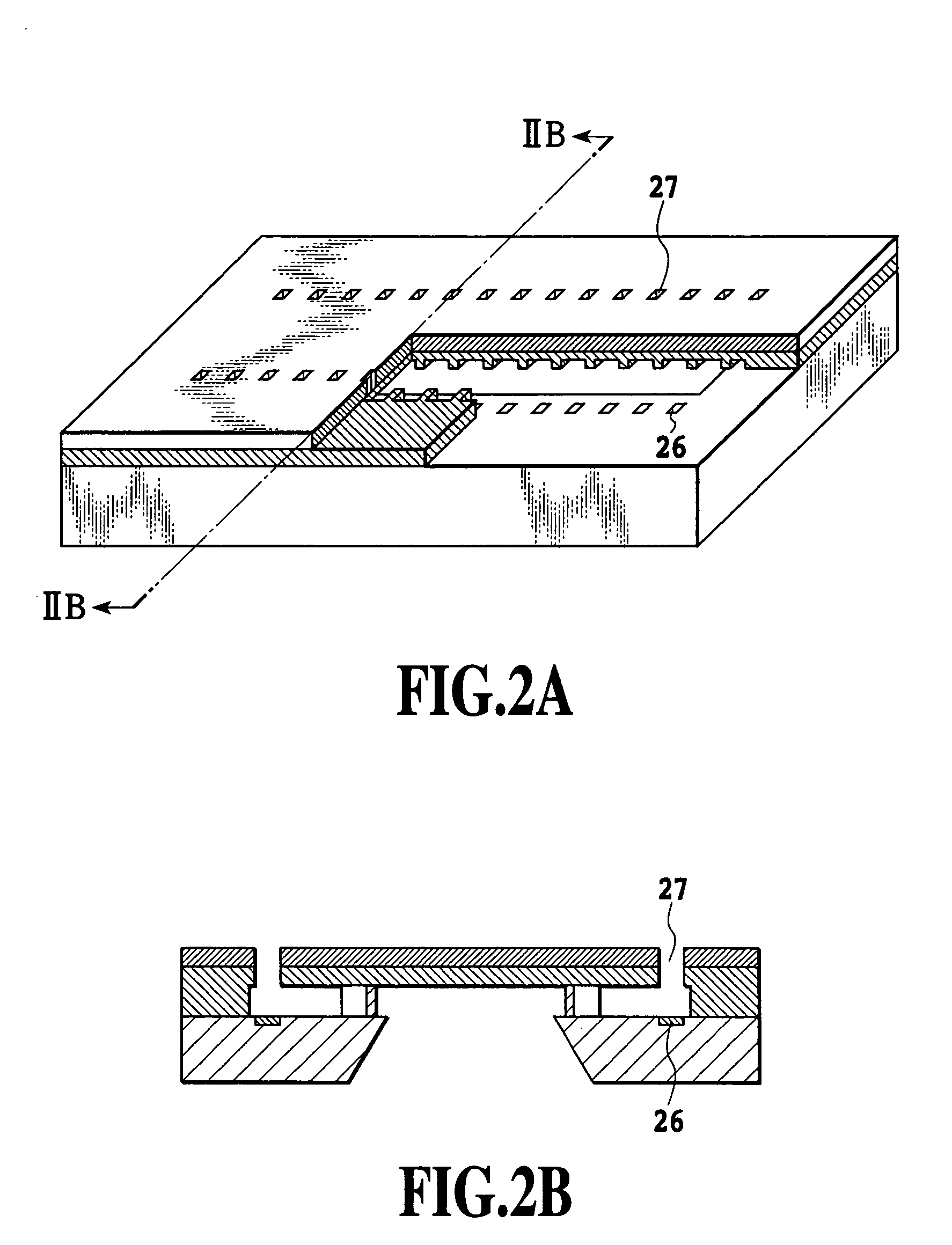
[0050]FIGS. 2A and 2B are views schematically showing an ejection opening structure (hereinafter, also called printing chip) of the printing head which ejects the ink of one color, in the inkjet printing head of the present embodiment, and FIG. 2A is its perspective view, and FIG. 2B is a view showing a sectional view of A–A′ line in FIG. 2A.

[0051]As shown in these views, this printing chip is an ink ejection section of the inkjet printing head which ejects the ink, and an inkjet printing means for ejecting the ink by using the thermal energy. That is, it has an electric thermal converter 26 for generating the thermal energy, and the thermal energy g...

embodiment 2

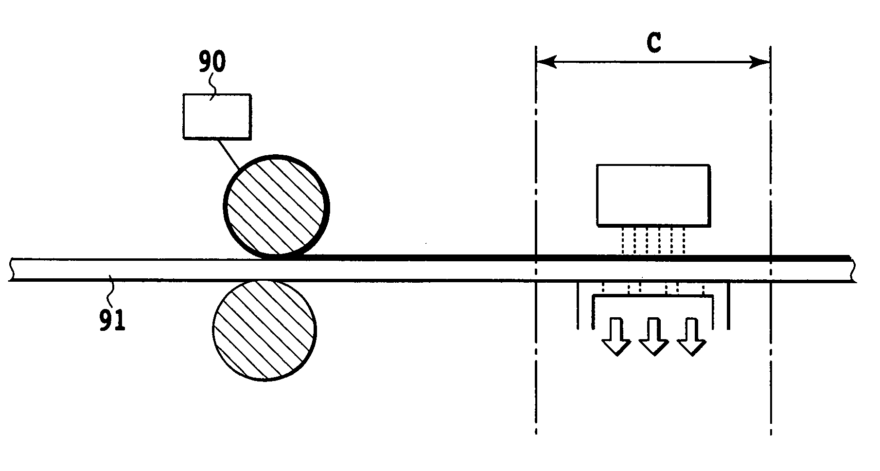
[0075]Next, the second embodiment of the present invention will be described. In the first embodiment, an example in which, during the suction, the suction force is constant and not changed, is described. That is, simultaneously with the time when the printing sheet is sucked, the suction force sucks the printing sheet by the suction force by which the ink solvent or water can be sucked. In contrast to this, in the present embodiment, the suction force changes in two steps, and it is determined that the suction force while the printing head scans the printing sheet and ejects the ink and reacting liquid onto the printing sheet, is weak, and after the scanning, the suction force up to the next scanning is stronger. Specifically, the suction force of the latter is made the same as that described in the first embodiment, and the permeation of the ink solvent is accelerated. Hereupon, because the structure of the printing chip, printing apparatus, recovery unit and the printing sheet su...

embodiment 3

[0081]The third embodiment of the present invention relates to the structure by which the sheet suction for the fixing acceleration is conducted at the position different from the scanning position by the printing head. The structure except for this suction position is substantially the same as the embodiments 1 and 2. However, a shape of the carriage and the printing head mounted on it is different (refer to FIG. 7).

[0082]FIG. 7 is a view showing the main structure of an ink-jet printer according to the present embodiment, and the same view as FIG. 1 shown relating to the embodiment 1. In the present embodiment, a pore for sucking the paper 10 is not provided in the platen 71, and the pore 72 is provided in the holding member for the fixing 73 positioned on the downstream side of the sheet discharge roller 79 on the sheet discharge side.

[0083]Next, the control of the fixing acceleration of the present embodiment will be described. In the case of the scanning by the printing head, t...


PUM


Abstract

In an inkjet printing apparatus, when a printing is performed by generating the reacting so that, on the printing sheet, permeation of an ink solvent is delayed to prevent that the fixing time is prolonged thereby. A printing sheet is sucked by the comparatively weak suction force in a degree in which the sheet is tightly contacted with the pore of the platen. Hereby, insolubilized or coagulated coloring matters and the ink solvent except the reactive radical component or water on the sheet are sucked together into the sheet, and then the forcible permeation condition is formed. As a result, the fixing time is shorter than in a case where there is no suction, and the fixing by the reactive system ink-set can be accelerated.

Description

[0001]This application claims priority from Japanese Patent Application Nos. 2003-065600 filed Mar. 11, 2003 and 2004-045384 filed Feb. 20, 2004, which are incorporated hereinto by reference.BACKGROUND OF THE INVENTION[0002]1. Field of the Invention[0003]The present invention relates to an inkjet printing apparatus and an inkjet printing method which perform a color printing by applying ink or a reacting liquid, which makes a coloring material in the ink insoluble or coagulated, to a printing sheet, which has an air permeability from an obverse side of the printing sheet to a reverse side thereof (excluding a medium having for example a resin coated layer and then having no air permeability), such as a plain paper, a printing sheet having an ink receiving layer, and a converted paper.[0004]2. Description of the Related Art[0005]Recently, in a field of an ink printing art, an ink jet printing method has been studied and put into practical use in place of conventional printing arts. T...

Claims


Application Information

Patent Timeline
Patent Type & Authority Patents(United States)
IPC IPC(8): B41J2/01B41J11/08B41J2/165B41J11/00
CPCB41J11/0085B41J11/0015
Inventor MATSUMOTO, NOBUYUKISUGAMA, SADAYUKISANADA, MIKIO
Owner CANON KK
Why Eureka
Try Eureka