Pole group inserting machine and use method thereof

A plug-in machine and extreme group technology, applied in the direction of sustainable manufacturing/processing, climate sustainability, final product manufacturing, etc., can solve problems such as low work efficiency, battery box deformation, heavy weight, etc., to save labor costs and improve The effect of production efficiency and convenient operation

Active Publication Date: 2019-08-02
TIANNENG GRP HENAN ENERGY TECH
View PDF11 Cites 0 Cited by
  • Summary
  • Abstract
  • Description
  • Claims
  • Application Information

AI Technical Summary

Problems solved by technology

In the process of battery production and assembly, it involves assembling multiple pole groups into the battery case. Since the overall thickness of the pole group is greater than the internal space of the battery case, the traditional operation is to manually put the pole groups into the clamping fixture in turn. , after being manually pressed, press it into the battery case once through the equipment. The disadvantages of the above operation are: 1. It is not suitable for automatic production, and there is a lot of lead dust in the clamping process, which affects the health of the staff; The work efficiency is low if the jigs are put in order; 3. Because the battery box is made of flexible material, it can deform when it is squeezed. Therefore, after putting in several pole groups first, the battery box will deform and cause the The remaining space in the box is narrow, and it is difficult to put in subsequent pole groups, and the distance between the cluster chambers in the battery box is small, which cannot provide space for the cluster clamping mechanism, and the transfer of the clamping jig is required, and the structure of the jig is complicated , the weight is heavy, and the manual frequent handling and clamping fixture is labor-intensive

Method used


Image

  • Pole group inserting machine and use method thereof
  • Pole group inserting machine and use method thereof
  • Pole group inserting machine and use method thereof

Examples


Embodiment Construction

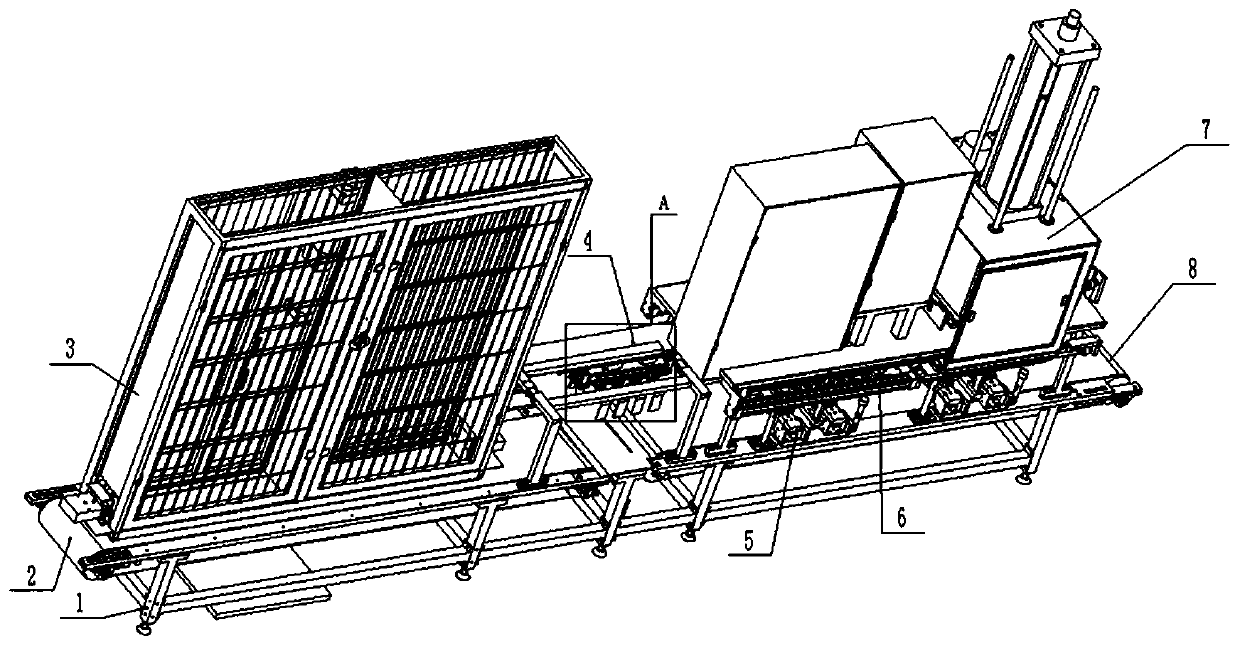
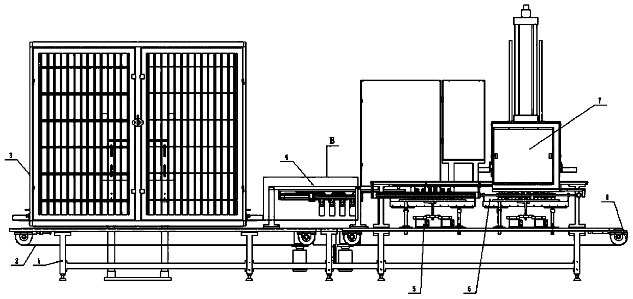
[0035] Such as Figure 1-2 As shown, a pole group inserting machine includes a frame 1, a first conveyor belt 2 and a second conveyor belt 8 are arranged on the frame 1, and a battery for supplying the first conveyor belt 2 is arranged on the frame 1 above the first conveyor belt 2 Shell feeding mechanism 1, the frame 1 between the first conveyor belt 2 and the second conveyor belt 8 is provided with a transfer mechanism 4 that transfers the battery case on the first conveyor belt 2 to the second conveyor belt 8, the second conveyor belt 8 The frame 1 above is provided with a plurality of stabilizing mechanisms 5 for stabilizing the battery case on the second conveyor belt 8, the frame 1 above the stabilizing mechanism 5 is provided with a movable plate 612, and a plurality of vertical plates 612 are fixed on the movable plate 612. The sixth cylinder 613 of the sixth cylinder, the telescopic rod of the sixth cylinder 613 is fixedly connected with the frame 1 below, the movable...


PUM


Abstract

The invention relates to the technical field of battery production equipment, and particularly relates to a pole group inserting machine and a use method thereof. The pole group inserting machine comprises a rack. A supplying mechanism for supplying a battery case to a first conveyor belt is arranged on the rack above the first conveyor belt. A transfer mechanism is arranged on the rack between the first conveyor belt and a second conveyor belt. A plurality of stabilization mechanisms for stabilizing the battery case on the second conveyor belt are arranged on the rack above the second conveyor belt. A pole group positioning mechanism is fixed on a movable plate. A pole group jacking mechanism is arranged above the pole group positioning mechanism. The pole group jacking mechanism is usedfor jacking the pole group in the pole group positioning mechanism into the battery case stabilized by the stabilization mechanisms, and the pole group jacking mechanism is slidably arranged on the rack. An anti-pole prevention device is arranged in the pole group jacking mechanism so that an alarm can be given when the pole group is placed upside down, the pole group lug of the pole group placedupside down is ensured not to be damaged by the jacking block, and the labor cost can be greatly saved and the production efficiency can be enhanced.

Description

technical field [0001] The invention relates to the technical field of battery production equipment, in particular to an electrode group inserting machine and a method for using the same. Background technique [0002] Lead-acid batteries are widely used in various important fields because of their low price, reliable quality, large capacity range, and long service life. In the process of battery production and assembly, it involves assembling multiple pole groups into the battery case. Since the overall thickness of the pole group is greater than the internal space of the battery case, the traditional operation is to manually put the pole groups into the clamping fixture in sequence. , after being manually pressed, press it into the battery case once through the equipment. The disadvantages of the above operation are: 1. It is not suitable for automatic production, and there is a lot of lead dust in the clamping process, which affects the health of the staff; The work effic...

Claims


Application Information

Patent Timeline
Patent Type & Authority Applications(China)
IPC IPC(8): H01M10/14
CPCH01M10/14Y02E60/10Y02P70/50
Inventor 赵海青梁庄雄欧阳万忠吴建祥
Owner TIANNENG GRP HENAN ENERGY TECH
Why Eureka
Try Eureka