Locking sheet, push-and-pull locking mechanism and connector with push-and-pull locking mechanism

A locking mechanism and locking piece technology are applied in the direction of connection, two-part connection device, and parts of the connection device, which can solve the problems of inconvenient operation and influence on work efficiency, and achieve the reduction of disassembly steps, the convenience of operation, and the improvement of The effect of work efficiency

Active Publication Date: 2019-08-02
CHINA AVIATION OPTICAL-ELECTRICAL TECH CO LTD
View PDF9 Cites 2 Cited by
  • Summary
  • Abstract
  • Description
  • Claims
  • Application Information

AI Technical Summary

Problems solved by technology

Whether it is in the locking operation or the separation operation, two manual steps are required: one is to press down or lift the force application part of the locking piece, and the other is to insert or pull the plug into the socket. The operation is very inconvenient and will cause Great impact on work efficiency

Method used


Image

  • Locking sheet, push-and-pull locking mechanism and connector with push-and-pull locking mechanism
  • Locking sheet, push-and-pull locking mechanism and connector with push-and-pull locking mechanism
  • Locking sheet, push-and-pull locking mechanism and connector with push-and-pull locking mechanism

Examples


Embodiment 1

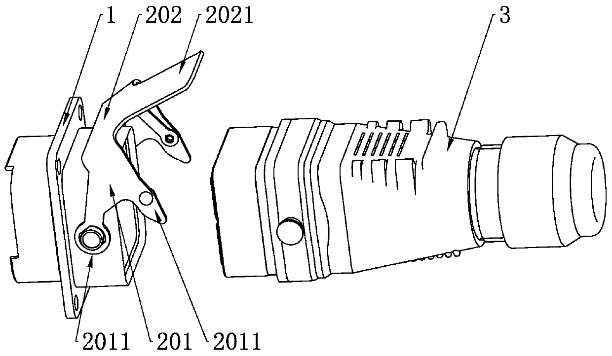
[0035] see figure 2 , a locking piece, has two connecting arms 201 oppositely arranged, a bridging portion 202 connecting the aforementioned two connecting arms 201, each end of the connecting arm 201 has a bending portion 203, and the bending portion is connected to the The end of the arm forms a groove 204 for snapping into the first protrusion 101 on the socket housing 1 or the second protrusion 301 on the plug housing 3 . The bridging portion 202 extends laterally and slopes downward to form a matching portion 205 , and the bent portion and the matching portion are located on two sides of the bridging portion. The two sides of the mating portion close to the bridging portion respectively extend downward to form a connecting portion 206, and the connecting portion 206 is provided with a shaft for passing through so as to install the locking piece on the socket housing 1 or the plug in a rotatable connection. The through hole 207 on the housing 3; the end of the matching p...

Embodiment 2

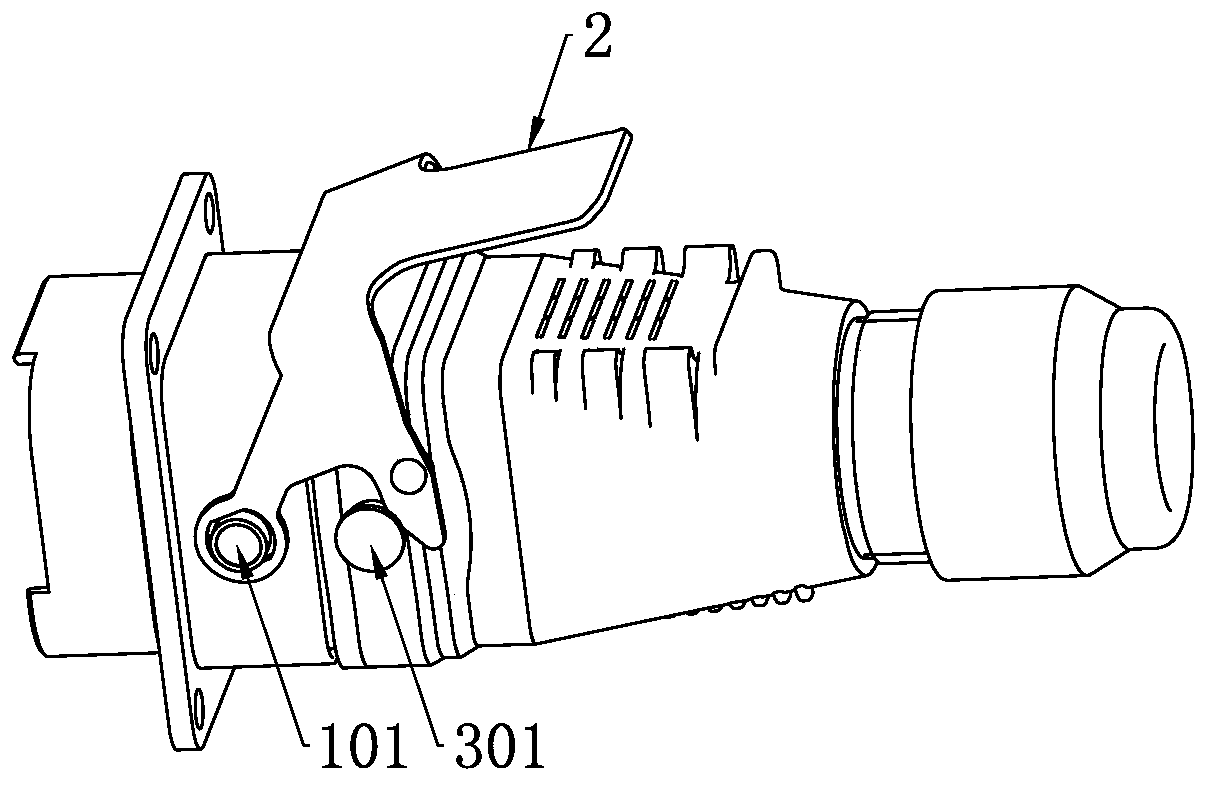
[0037]On the basis of Embodiment 1, the present invention proposes a push-pull locking mechanism, which includes a locking piece 2, a rotating shaft, an elastic member, a moving piece, and a limiter. The locking piece 2 includes two connecting arms 201 arranged opposite to each other. 1. The bridging portion 202 connecting the aforementioned two connecting arms, the end of each connecting arm 201 forms a bent portion 203, and the bent portion and the end of the connecting arm form a first protrusion for limiting the socket housing. or the second protruding groove 204 on the plug housing; the bridging portion 202 extends laterally and slopes downward to form a matching portion 205, and the two sides of the matching portion close to the bridging portion respectively extend downward to form a through hole 207 The connection part 206. The rotating shaft is used to pass through the through hole 207 of the connecting part and the step 302 on the socket housing or the plug housing, s...

Embodiment 3

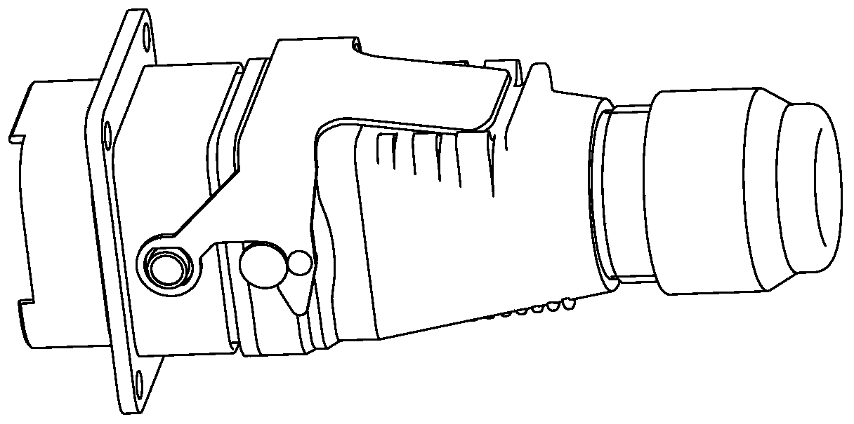
[0042] see image 3 and Figure 4 , on the basis of Embodiment 2, the present invention proposes a connector using a push-pull locking mechanism, including a socket, a plug and a push-pull locking mechanism. Both sides of the socket housing 1 are provided with first protrusions 101, and the plug The housing is provided with a step 302 , and the push-pull locking mechanism includes a locking plate 2 , a pin shaft 4 , a torsion spring 6 , a sleeve 7 and a block 8 . The push-pull locking mechanism is integrally installed on the plug housing, that is, the pin shaft 4 passes through the step 302, the through hole 207 and the torsion spring 6 to install the locking piece 2 on the plug housing 3 in a rotatable connection, and the lock The two connecting arms 201 of the tight piece 2 are respectively located on two sides of the plug housing, and the groove 204 faces the first protrusion 101 on the same side of the socket housing. The two force arms of the torsion spring 6 are respec...


PUM


Abstract

A push-and-pull locking mechanism comprises a locking sheet, a movement member, a protruded part, an elastic member and a limiting member. The locking sheet is mounted on a socket casing or a plug casing in a rotatable connection manner; the movement member mounted on the socket casing or the plug casing and capable of moving horizontally relative to the socket casing or the plug casing; the protruded part is arranged in the end portion of the movement member, cooperates with an inclined surface of a cooperation part by abutting, and enables the locking sheet to rotate when a socket is separated from a plug; one end of the elastic member is connected with the locking sheet, the other end of the elastic member is connected with the socket casing or plug casing, and the elastic member enables the locking sheet to return to the original position automatically after rotation; and the limiting member is mounted on the socket casing or plug casing, and limit horizontal movement of the movement member. When the push-and-pull locking mechanism is used to lock the socket and plug, it is only required to insert the plug into the socket, and when the socket is separated from the plug, it is only required to pull the movement member; and compared with the prior art, operation is simple, dismounting steps can be reduced, and the working efficiency is improved. The locking sheet and movementmember can both return the original positions after operation.

Description

technical field [0001] The invention belongs to the technical field of connectors, and in particular relates to a locking piece, a push-pull locking mechanism using the locking piece and a connector using the push-pull locking mechanism. Background technique [0002] In the prior art, the locking of the socket and the plug is realized by manually operating the locking piece. see Figure 1A to Figure 1C , the existing locking piece 2 has two connecting arms 201 arranged oppositely, and a bridging portion 202 connecting the aforementioned two connecting arms. The other end 2011 is hinged with the first protrusion 101 on the socket housing and is close to the plug housing 3 for matching with the second protrusion 301 on the plug housing; When locking the socket and the plug, the end of the connecting arm close to the socket housing is sleeved on the first protrusion on the same side of the socket housing, so that the locking piece straddles the socket and can be positioned rel...

Claims


Application Information

Patent Timeline
Patent Type & Authority Applications(China)
IPC IPC(8): H01R24/00H01R13/627H01R13/629
CPCH01R13/627H01R13/629H01R24/00
Inventor 李立新崔艳磊张志中邹宏飞柳先波
Owner CHINA AVIATION OPTICAL-ELECTRICAL TECH CO LTD
Why Eureka
Try Eureka