
Conditioning method and system for dispensing chemical products

A technology for chemical products and adjustment methods, applied in chemical instruments and methods, control/manipulation systems, water treatment parameter control, etc., to avoid environmental damage, ensure safety, and reduce process costs

Active Publication Date: 2022-07-22
赛高股份公司
View PDF4 Cites 0 Cited by
  • Summary
  • Abstract
  • Description
  • Claims
  • Application Information

AI Technical Summary

Problems solved by technology

[0015] This problem is solved by a method and a system according to the independent method and system claims respectively

Method used


Image

  • Conditioning method and system for dispensing chemical products
  • Conditioning method and system for dispensing chemical products

Examples


Embodiment Construction

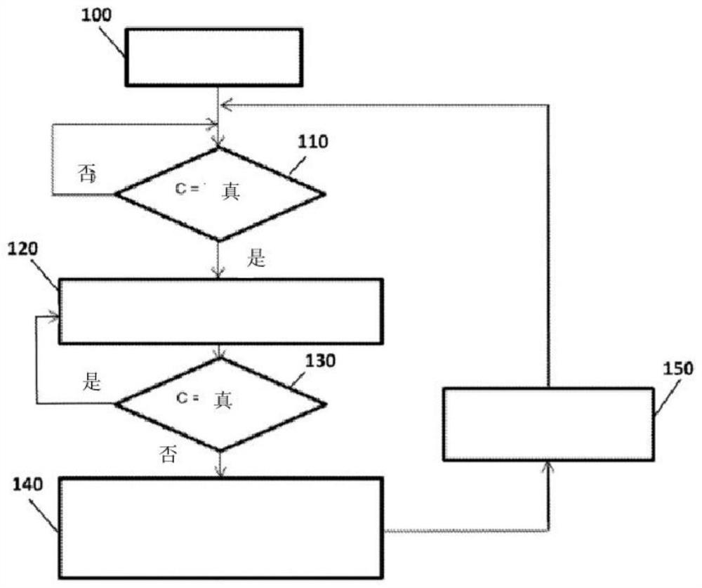
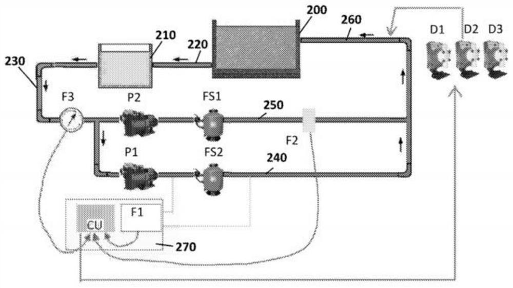
[0025] figure 1 The conditioning system shown is suitable for the circulation circuit of the swimming pool 200 , including the compensation tank 210 connected to the swimming pool 200 by a drain pipe 220 . The compensation tank 210 is connected to the circulating hydraulic circuit through the outlet pipe 230, and the circulating hydraulic circuit includes a first branch 240 and a second branch 250 connected in parallel between the outlet pipe 230 and the inlet pipe 260, wherein the inlet pipe 260 connects the circulating hydraulic circuit to the swimming pool 200 . The first branch 240 is provided with a corresponding (first) circulating pump PI, a filter FS2 (optionally a sand filter), which is advantageously located downstream of this circulating pump PI; similarly, the second branch 250 is provided with A corresponding (second) circulating pump P2, a filter FS1 (optionally a sand filter), is advantageously located downstream of this circulating pump P2. The circulation pu...


PUM


Abstract

A regulating method for regulating the distribution of at least one chemical product in a circulating hydraulic circuit having one or more branches (230, 240, 250), wherein at least one distribution device (D1, D2, D3) is configured to Dispensing at least one corresponding chemical product in the circulating hydraulic circuit when activated, comprising the steps of: detecting one or more corresponding branches of the circulating hydraulic circuit by means of one or more corresponding flow sensor means (F1, F2, F3) one or more liquid flow rates in circuits (230, 240, 250); wherein, if said one or more detected branches (230, 240, 250) of said one or more corresponding branches (230, 240, 250) of the circulating hydraulic circuit The occurrence of a plurality of regular conditions of liquid flow rates not below or above the respective flow rate thresholds allows activation of said at least one distribution device (D1, D2, D3), and if present by said one or more of the circulating hydraulic circuits an error condition caused by at least one of the one or more liquid flow rates detected in at least one of the corresponding branches (230, 240, 250) being below or not above the corresponding flow threshold, then disabling the at least one dispensing device (D1, D2, D3) is activated for a time equal to the recovery time (T) plus the additional disable time (T1; T2; T3) associated with the at least one flow sensor device (F1, F2, F3), The at least one detected liquid flow rate that resulted in the error condition is restored to a value not below or above the corresponding flow rate threshold at the recovery time (T).

Description

technical field [0001] The present invention relates to a method and system for regulating the distribution of one or more chemical products in a hydraulic circuit, in particular a method and system for controlling the distribution of one or more chemical products in a circulating circuit of a swimming pool. Background technique [0002] Although in the following reference will be made mainly to the circulation circuit of a swimming pool, it should be understood that the method and system according to the invention can also be applied to different hydraulic circuits, such as in particular in bathtubs, hot tubs, hydromassage tubs and therapeutic tubs. hydraulic circuits which still fall within the scope of protection defined by the appended claims. [0003] Swimming pool water is usually taken from water pipes and therefore has hygienic / bacterial properties suitable for keeping swimmers safe. For economical and environmental reasons, it is not possible to continuously empty ...

Claims


Application Information

Patent Timeline
Patent Type & Authority Patents(China)
IPC IPC(8): C02F1/68C02F103/42
CPCC02F1/008C02F2103/42C02F2209/003C02F2209/006C02F2209/40C02F2301/046C02F1/685
Inventor 克里斯蒂安·克雷亚蒂路易吉诺·埃斯波西托阿德里奥·潘塔莱奥尼
Owner 赛高股份公司
Learn More