Automatic cutting liquid adding robot of machine tool
A technology of automatic addition and cutting fluid, applied in the direction of manipulator, metal processing equipment, metal processing machine parts, etc., can solve the problem of inconvenient control of the addition amount, etc., to achieve the effect of convenient and precise injection
- Summary
- Abstract
- Description
- Claims
- Application Information
AI Technical Summary
Problems solved by technology
Method used
Image

Examples
Embodiment 1
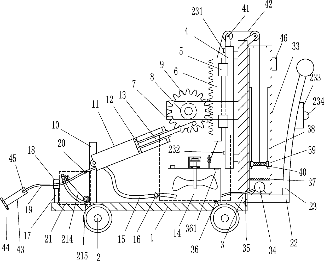
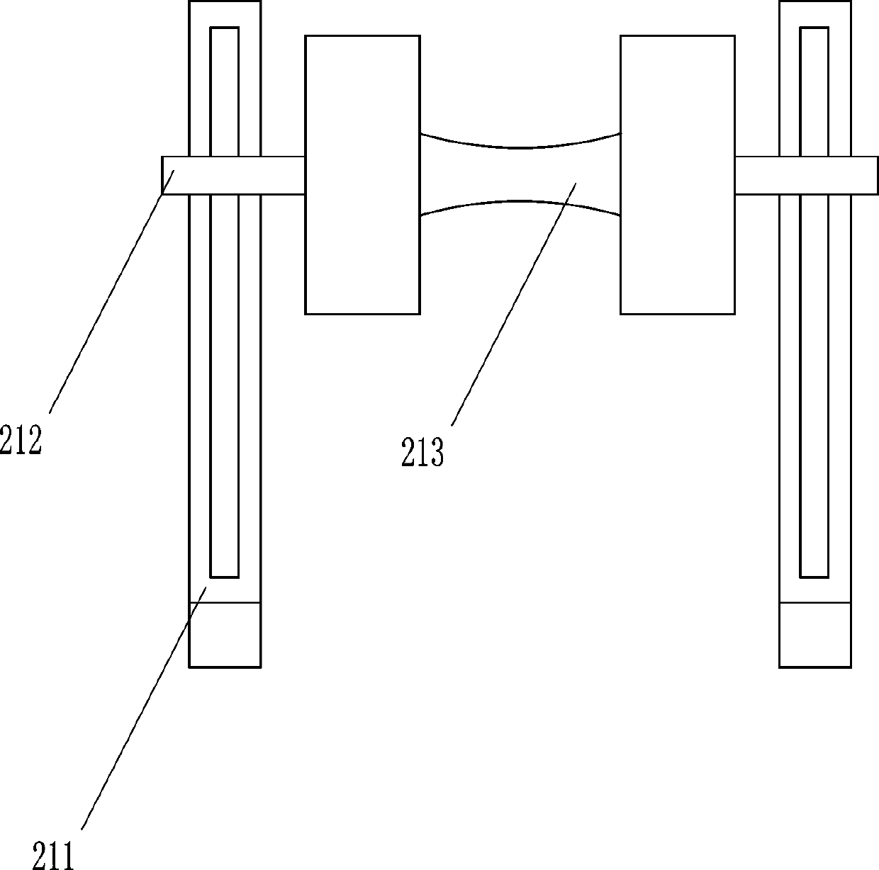
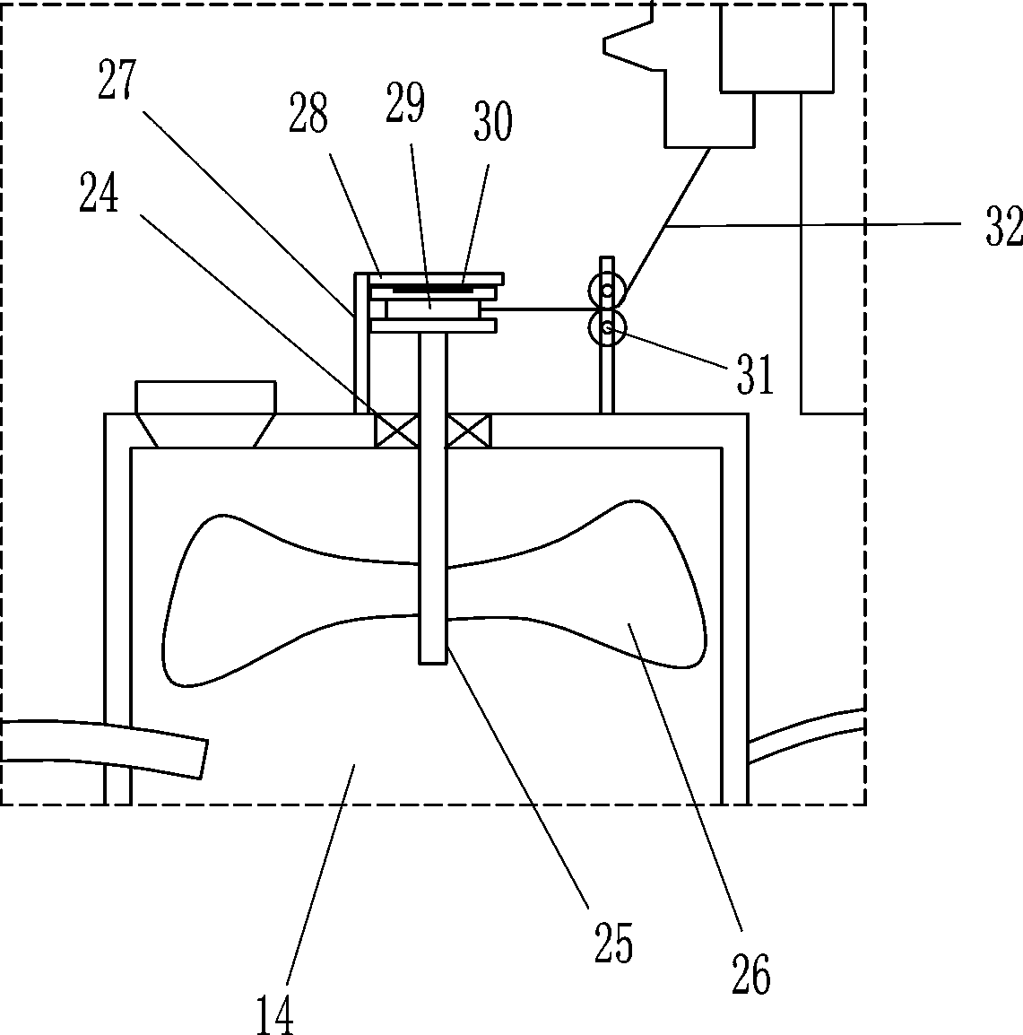
[0018] A machine tool cutting fluid automatic adding robot, such as Figure 1-4 As shown, it includes base plate 1, wheel 2, mounting plate 3, straight slide rail 4, straight slide block 5, rack 6, first fixed plate 7, rotating motor 8, gear 9, second fixed plate 10, cylinder 11. Piston 12, connecting rod 13, box body 14, hose 15, first one-way valve 16, first connecting rod 17, guide sleeve 18, nozzle 19, second one-way valve 20, clamping device 21, The third fixed plate 22, the push handle 23, the first travel switch 231, the second travel switch 232, the control box 233 and the main switch 234; The mounting plate 3 and the bottom plate 1 are connected to the mounting plate 3 by means of bolts. The upper left side of the mounting plate 3 is connected with a straight slide rail 4, and the straight slide rail 4 is slidably connected with two straight slide blocks 5. The left side is connected with a rack 6, the upper left side of the mounting plate 3 is connected with a first...
Embodiment 2
[0020] A machine tool cutting fluid automatic adding robot, such as Figure 1-4As shown, it includes base plate 1, wheel 2, mounting plate 3, straight slide rail 4, straight slide block 5, rack 6, first fixed plate 7, rotating motor 8, gear 9, second fixed plate 10, cylinder 11. Piston 12, connecting rod 13, box body 14, hose 15, first one-way valve 16, first connecting rod 17, guide sleeve 18, nozzle 19, second one-way valve 20, clamping device 21, The third fixed plate 22, the push handle 23, the first travel switch 231, the second travel switch 232, the control box 233 and the main switch 234; Mounting plate 3, the upper left side of the mounting plate 3 is connected with a straight slide rail 4, two straight sliders 5 are slidably connected on the straight slide rail 4, the left side of the straight slider 5 is connected with a rack 6, and the left side of the mounting plate 3 The upper part is connected with the first fixed plate 7, the first fixed plate 7 is located beh...
Embodiment 3
[0023] A machine tool cutting fluid automatic adding robot, such as Figure 1-4 As shown, it includes base plate 1, wheel 2, mounting plate 3, straight slide rail 4, straight slide block 5, rack 6, first fixed plate 7, rotating motor 8, gear 9, second fixed plate 10, cylinder 11. Piston 12, connecting rod 13, box body 14, hose 15, first one-way valve 16, first connecting rod 17, guide sleeve 18, nozzle 19, second one-way valve 20, clamping device 21, The third fixed plate 22, the push handle 23, the first travel switch 231, the second travel switch 232, the control box 233 and the main switch 234; Mounting plate 3, the upper left side of the mounting plate 3 is connected with a straight slide rail 4, two straight sliders 5 are slidably connected on the straight slide rail 4, the left side of the straight slider 5 is connected with a rack 6, and the left side of the mounting plate 3 The upper part is connected with the first fixed plate 7, the first fixed plate 7 is located be...
PUM
 Abstract
Description
Claims
Application Information
 - R&D
- Intellectual Property
- Life Sciences
- Materials
- Tech Scout
- Unparalleled Data Quality
- Higher Quality Content
- 60% Fewer Hallucinations
Browse by: Latest US Patents, China's latest patents, Technical Efficacy Thesaurus, Application Domain, Technology Topic, Popular Technical Reports.
© 2025 PatSnap. All rights reserved.Legal|Privacy policy|Modern Slavery Act Transparency Statement|Sitemap|About US| Contact US: help@patsnap.com