Three-working-face bridge erecting machine capable of achieving longitudinal and transverse splicing and bent cap shortcut-free segment splicing method

A technology of working face and bridge erection machine, which is applied in the erection/assembly of bridges, bridges, bridge construction, etc., can solve the problems of increasing the force of the main girder, difficult to hoist, difficult to achieve, etc., and achieves strong adaptability, high efficiency and high benefit. Effect

Pending Publication Date: 2019-08-06
ZHEJIANG PROVINCIAL INST OF COMM PLANNING DESIGN & RES CO LTD
View PDF0 Cites 7 Cited by
  • Summary
  • Abstract
  • Description
  • Claims
  • Application Information

AI Technical Summary

Problems solved by technology

[0005] When the width of the bridge increases (8 lanes or even 10 lanes) or there is space utilization under the bridge, the size of the pier cover girder is large and the cantilever range is enlarged. At this time, the weight of the entire pier cover girder is very heavy. , the use of the above-mentioned double-face bridge erecting machine will cause many problems: on the one hand, when the weight of the prefabricated parts of the prefabricated main girder, cover beam and pier column is close to and within a certain range, the effect of the bridge erecting machine is the most significant, If the weight of the prefabricated cover girder is too large, it may be difficult to hoist, or cause economic benefits to decline; The beam is placed along the longitudinal direction of the bridge, and after being hoisted, it is rotated in the air in the plane, and then positioned and placed with the pier column. Therefore, when the size and weight of the cover beam are large, it will increase the difficulty of the plane rotation operation, and there is a certain risk; On the one hand, when the weight of the prefabricated cover girder is very large, the force on the main girder will be increased during the transportation of the bridge deck, which will be detrimental to the safety of the main girder during the construction process.
In addition, when the prefabricated cover girder is assembled in segments, certain measures need to be taken to ensure the structural stability and positioning accuracy of the cover girder segments during the assembly process, which is difficult to achieve with the existing double-face integrated bridge erecting machine.

Method used


Image

  • Three-working-face bridge erecting machine capable of achieving longitudinal and transverse splicing and bent cap shortcut-free segment splicing method
  • Three-working-face bridge erecting machine capable of achieving longitudinal and transverse splicing and bent cap shortcut-free segment splicing method
  • Three-working-face bridge erecting machine capable of achieving longitudinal and transverse splicing and bent cap shortcut-free segment splicing method

Examples


Embodiment 1

[0049] The following is a case to describe the assembly method of the cover beam without access road segment using this three-face bridge erection machine. The specific steps are as follows:

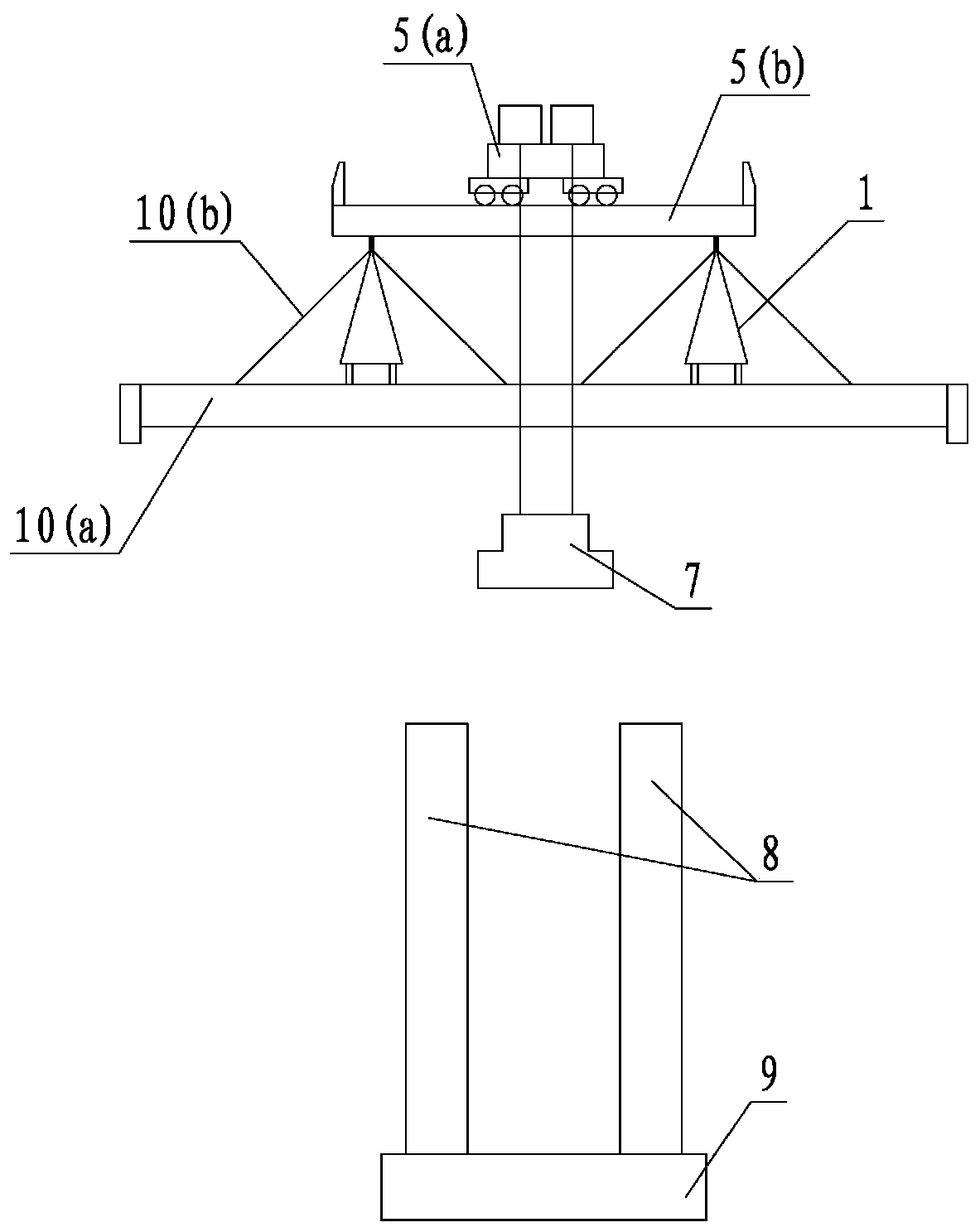
[0050] Step 1: As shown in Figure 5(a), after the erection of the prefabricated piers 8 is completed, the prefabricated cover girder segment N1 is transported through the bridge deck, hoisted by the bridge erection crane 5 and transported longitudinally to the transverse direction of the prefabricated cover girder segment. Assemble the work surface.

[0051] Step 2: As shown in Figure 5(b), the cover beam segment N1 is transferred to the beam 10(a) through the mechanical transfer device of the transverse beam, and the segment N1 is moved laterally to the beam 10(a) through the rail of the beam 10(a). When the crane 5 of the bridge erecting machine moves back and lifts the next segment N2, the above process can be performed synchronously to improve the erection efficiency.

[0052] Step ...

Embodiment 2

[0058] The three-face bridge erecting machine of the present invention can be adapted to different types of cover beam segment assembly processes, such as Figure 6(a) ~ Figure 6(f) As shown, this embodiment is different from the aforementioned balanced cantilever lateral assembling method. This method adopts the all-plastic assembling method, uses slings as temporary supports, and finally tensions all the prestressing beams at one time. The construction accuracy is required to be high, and the specific steps are as follows:

[0059] Step 1: As shown in Figure 6(a), after the erection of the prefabricated piers 8 is completed, the prefabricated cover beam segment N1 is transported through the bridge deck, and is lifted by the bridge erection crane 5 and transported longitudinally to the horizontal direction of the prefabricated cover beam segment. Assemble the work surface.

[0060] Step 2: As shown in Fig. 6(b), the cover beam segment N1 is transferred to the beam 10(a) thro...


PUM


Abstract

The invention discloses a three-working-face bridge erecting machine capable of achieving longitudinal and transverse splicing and a bent cap shortcut-free segment splicing method. Double-working-surface erection of a bridge pier stand column and an upper structure main beam is realized and a prefabricated bent cap segment transverse assembly working face is additionally arranged, so assembly of the shortcut-free segment of the bent cap can be achieved through the working face, and in other words, in the bent cap segment assembly process, the structural stability and positioning accuracy of the bent cap segment can be guaranteed without arranging temporary shortcuts or brackets and the like. According to the invention, it can be achieved that the prefabricated pier column can be erected inthe vertical direction, the prefabricated bent cap segments can be transversely spliced, the prefabricated main beams can be longitudinally erected, and repeated disassembling and assembling of facilities such as temporary shortcuts or brackets are not required for transverse splicing of the bent cap segments.

Description

technical field [0001] The invention belongs to the technical field of bridge engineering, and in particular relates to a three-working-face bridge erecting machine capable of realizing vertical and horizontal assembly and a method for assembling a cover beam without access road segments. Background technique [0002] The fully prefabricated assembly process of land bridges has been gradually promoted and applied in my country. The erection methods of prefabricated pier columns, cover beams and main beams mainly include crawler cranes or truck cranes, as well as the relatively new integrated bridge erection. The integrated bridge erecting machine has been applied for the first time in the main passage project of Ningbo Zhoushan Port. This bridge erecting machine uses the already erected bridge span as the channel for supporting and transporting prefabricated components, moves along the route and gradually assembles the remaining bridge spans, reducing The temporary land acqu...

Claims


Application Information

Patent Timeline
Patent Type & Authority Applications(China)
IPC IPC(8): E01D21/00
CPCE01D21/00
Inventor 李磊庄万律魏益峰王昌将陈向阳
Owner ZHEJIANG PROVINCIAL INST OF COMM PLANNING DESIGN & RES CO LTD
Why Eureka
Try Eureka