Printer nozzle cleaning and flying ink suction device

A technology of printers and nozzles, applied in printing devices, printing, etc., can solve the problems of complex overall design, increase the load of the lifting motor, increase the lifting weight of the machine head, etc., and achieve the effect of shortening the length of the whole machine

Active Publication Date: 2020-07-03
KEDA INDUSTRIAL GROUP CO LTD
View PDF14 Cites 2 Cited by
  • Summary
  • Abstract
  • Description
  • Claims
  • Application Information

AI Technical Summary

Problems solved by technology

In addition, the ink tray uses the timing belt to pull the ink from both sides of the machine to the bottom of the nozzle for a long distance. The overall design is complex, the cost is high, the stability is low, and the stroke is long, which increases the time required for the cleaning process;
[0003] In addition, the air suction slot is fixed on the machine head, and it rise

Method used


Image

  • Printer nozzle cleaning and flying ink suction device
  • Printer nozzle cleaning and flying ink suction device

Examples


Embodiment Construction

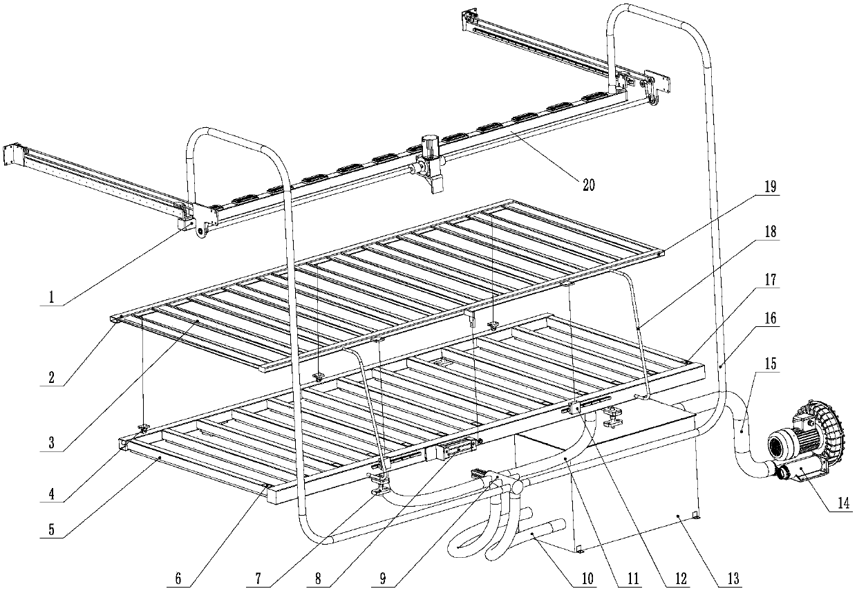
[0024] The invention provides a printer nozzle cleaning and ink flying device, such as figure 1 As shown, it includes nozzle cleaning beam assembly, ink receiving assembly, suction groove assembly, suction switching valve assembly and centrifugal fan; said nozzle cleaning beam assembly includes nozzle cleaning component 1, fixed beam 20 and cleaning suction pipe 16, wherein , the fixed crossbeam 20 is fixedly connected on the frame, and the upper surface of the nozzle cleaning part 1 is provided with a slit. The so-called upper surface refers to the upper surface in the direction shown in the figure, that is, when the nozzle is cleaned, the surface facing the nozzle , the slit is for sucking ink on the surface of the nozzle, the nozzle cleaning part includes a hollow cavity, and the inside of the fixed beam 20 also includes a hollow cavity, and the above two hollow cavities communicate, so that all The nozzle cleaning component 1 communicates with the fixed beam 20 , so when t...


PUM


Abstract

The invention relates to a printer nozzle cleaning and flying ink suction device. The printer nozzle cleaning and flying ink suction device comprises a nozzle cleaning cross beam assembly, an ink receiving assembly, an air suction groove assembly, an air suction switching valve assembly and a centrifugal fan. The ink receiving assembly comprises a plurality of ink receiving discs. The ink receiving discs are fixed to an ink receiving disc collecting pipe. The ink receiving disc assembly is contained in a machine head channel, the space of a whole machine is greatly utilized, and the length ofthe whole machine is reduced. The air suction groove assembly and the ink receiving disc assembly are fixed in a whole set, the lifting weight of a machine head is reduced, and the load of a lifting motor is reduced. The printer nozzle cleaning and flying ink suction device further comprises a gas-liquid separation box, all ink is collected into the gas-liquid separation box to be treated, then treated gas is exhausted to the atmosphere through the centrifugal fan, and therefore pollution to the environment is reduced.

Description

technical field [0001] The invention relates to the field of ceramic inkjet printers, in particular to a device for cleaning nozzles of a printer and absorbing flying ink. Background technique [0002] The existing ink-jet printer ink receiving tray is divided into 2 pieces, and the starting position is on the left and right sides of the machine head. When ink needs to be connected, the power source drives the timing belt, and the timing belt drives the ink tray to pull the ink tray from both sides of the machine to the bottom of the nozzle for ink connection, which increases the length of the machine. In addition, the ink tray uses the timing belt to pull the ink from both sides of the machine to the bottom of the nozzle for a long distance. The overall design is complex, the cost is high, the stability is low, and the stroke is long, which increases the time required for the cleaning process; [0003] In addition, the air suction slot is fixed on the machine head, and it ...

Claims


Application Information

Patent Timeline
IPC IPC(8): B41J2/165B41J2/17B41J29/17
CPCB41J2/16517B41J2/1721B41J29/17B41J2002/1728B41J2/165B41J2/17
Inventor 温干前彭钜欢覃立宇林锦袁
Owner KEDA INDUSTRIAL GROUP CO LTD
Why Eureka
Try Eureka