
Pipeline ball valve for crude oil delivery based on differential pressure extraction and siphon complete discharge

A siphon and pipeline technology, applied in the direction of siphon pipes, valve devices, cocks including cutting devices, etc., can solve the problems of reducing pipe diameter, counting deviation, reducing control flexibility, etc., to achieve the effect of ensuring flexibility and reducing deviation

Active Publication Date: 2019-08-06
象山宇翔机械有限公司
View PDF5 Cites 1 Cited by
  • Summary
  • Abstract
  • Description
  • Claims
  • Application Information

AI Technical Summary

Problems solved by technology

[0005] Aiming at the deficiencies in the prior art, the purpose of the present invention is to provide a pipeline ball valve for crude oil transportation based on differential pressure extraction and siphon exhaustion, so as to solve the problems of the ball valve in the prior art, because the temperature will rise during crude oil refining, which has better performance. However, due to the structural characteristics of the ball valve, part of the crude oil will remain inside the sphere and between the gaps when the flow is cut off. As the temperature decreases, the crude oil becomes viscous and adheres to the sphere to reduce its pipe diameter. At the same time The crude oil remaining in the gap will make the ball difficult to rotate and reduce its control flexibility; the flow of oil is usually counted, but due to the residual effect of the ball valve, the count has a certain deviation.

Method used


Image

  • Pipeline ball valve for crude oil delivery based on differential pressure extraction and siphon complete discharge
  • Pipeline ball valve for crude oil delivery based on differential pressure extraction and siphon complete discharge
  • Pipeline ball valve for crude oil delivery based on differential pressure extraction and siphon complete discharge

Examples


Embodiment Construction

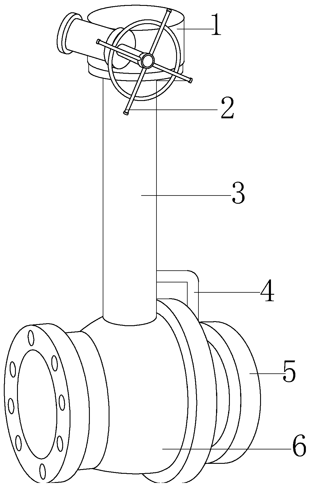
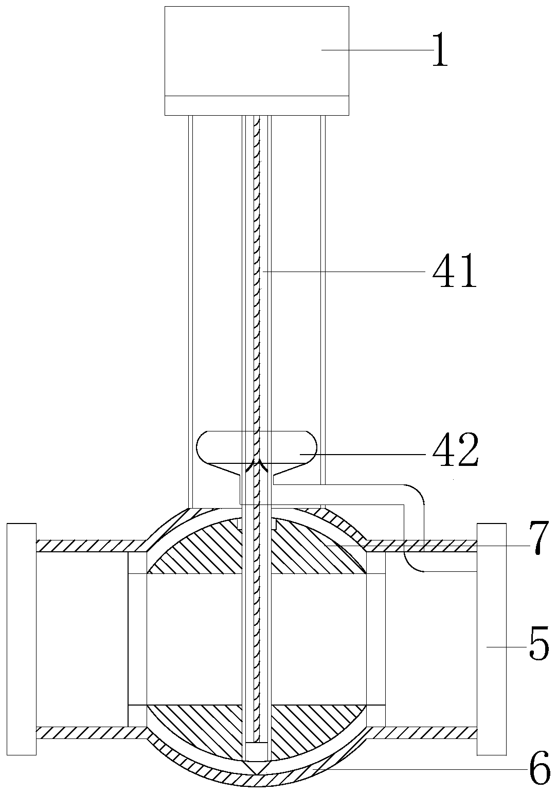
[0027] In order to make the technical means, creative features, goals and effects achieved by the present invention easy to understand, the present invention will be further described below in conjunction with specific embodiments.

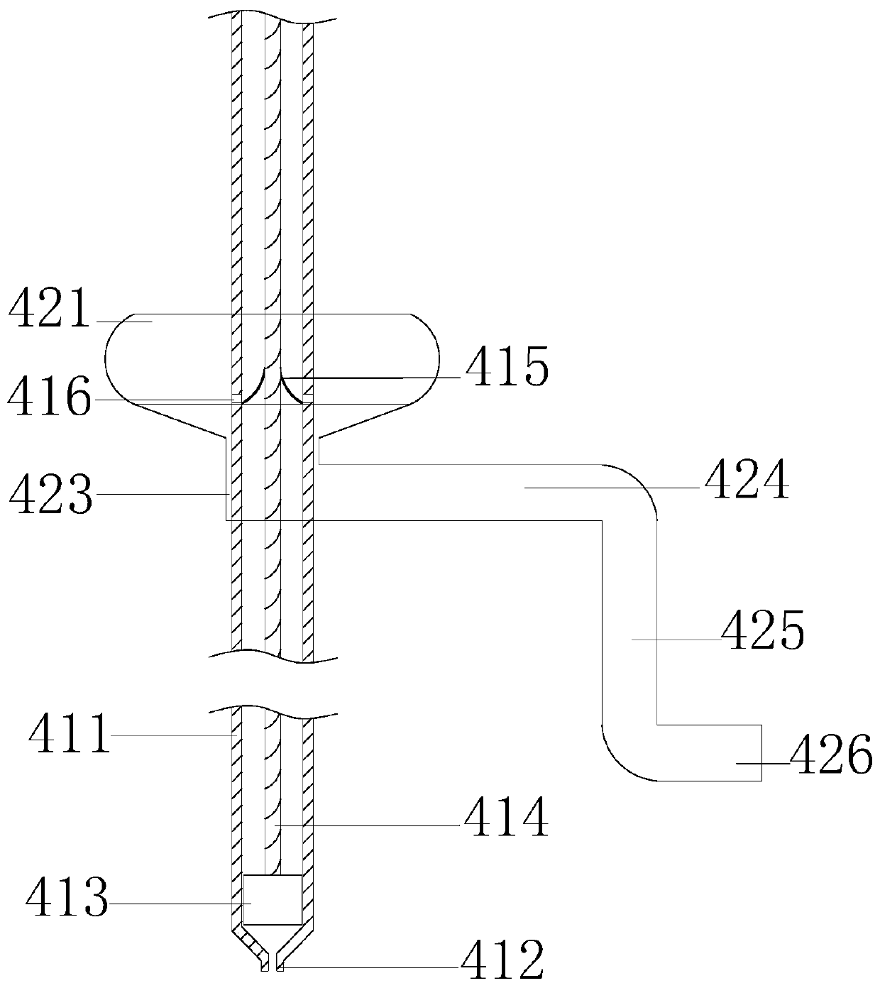
[0028] Such as Figure 1-Figure 4 As shown, the present invention provides a technical scheme of a pipeline ball valve for crude oil transportation based on differential pressure extraction and siphon exhaustion:

[0029] A pipeline ball valve for crude oil transportation based on differential pressure extraction and siphon exhaustion, the structure of which includes an actuator 1, a control hand wheel 2, a valve stem 3, a suction exhaustion device 4, a connecting flange 5, a valve body 6, a ball 7. The executive mechanism 1 is set on the upper end of the valve stem 3, the control handwheel 2 is engaged and movably connected with the actuator 1, and the suction exhaust device 4 is set inside the valve stem 3 and connected through electric welding....


PUM


Abstract

The invention discloses a pipeline ball valve for crude oil delivery based on differential pressure extraction and siphon complete discharge. The pipeline ball valve structurally comprises an executing mechanism, a control hand wheel, a valve rod, a suction complete discharging device, a connecting flange, a valve body and a ball body, wherein the executing mechanism is arranged at the upper end of the valve rod, the control hand wheel is movably connected to the executing mechanism in a meshed mode, the suction complete discharging device is arranged inside the valve rod and is in communication with the valve body through electric welding, and the lower end of the valve rod is in communication with the valve body through electric welding. According to the pipeline ball valve, the suctioncomplete discharging device is arranged, and through a differential pressure extraction and siphon mode, when the ball valve is closed, the crude oil remaining in gaps between the ball body and the ball body, and between the ball body and the valve body can be discharged, so that after the temperature is reduced, the crude oil is sticky and adhered to the inner wall and the outer wall of the ballbody, the pipe diameter of the flow of the ball body is ensured, meanwhile, the flexibility of the ball body during rotation can be ensured, and the deviation of crude oil metering can be reduced.

Description

technical field [0001] The invention relates to the field of ball valves, more precisely, a pipeline ball valve for crude oil transportation based on differential pressure extraction and siphon exhaustion. Background technique [0002] Ball valve refers to the valve whose opening and closing part (ball) is driven by the valve stem and rotates around the axis of the ball valve. The channels are connected and widely used in various fields. However, the pipeline ball valve of the prior art has the following defects: [0003] 1. The temperature of crude oil will rise during refining, and it has good fluidity. However, due to the structural characteristics of the ball valve, part of the crude oil will remain inside the ball and between the gaps when the flow is closed. As the temperature decreases, the crude oil becomes viscous. Sex, adhesion in the sphere reduces its pipe diameter, and the crude oil remaining in the gap will make the sphere difficult to rotate and reduce its c...

Claims


Application Information

Patent Timeline
Patent Type & Authority Applications(China)
IPC IPC(8): F16K5/06F16K5/08F04F10/00
CPCF04F10/00F16K5/0605F16K5/08
Inventor 周翔
Owner 象山宇翔机械有限公司
Learn More