A microchannel heat exchanger

A micro-channel heat exchanger and micro-channel technology, applied in heat exchange equipment, lighting and heating equipment, evaporator/condenser, etc., can solve the problems of not solving the drainage problem of the evaporator and reducing the heat exchange efficiency , to achieve the effect of solving drainage problems, improving heat exchange efficiency and optimizing design

Active Publication Date: 2021-09-28
ZHEJIANG DUNAN MASCH CO LTD
View PDF6 Cites 0 Cited by
  • Summary
  • Abstract
  • Description
  • Claims
  • Application Information

AI Technical Summary

Problems solved by technology

However, due to structural limitations, the microchannel heat exchanger with a common type of heat dissipation structure did not solve the drainage problem of the evaporator. Reduced heat transfer efficiency due to fin area

Method used


Image

  • A microchannel heat exchanger
  • A microchannel heat exchanger
  • A microchannel heat exchanger

Examples


Embodiment Construction

[0027] Embodiments of the invention are described in detail below, but the invention can be practiced in many different ways as defined and covered by the claims.

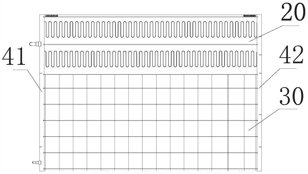
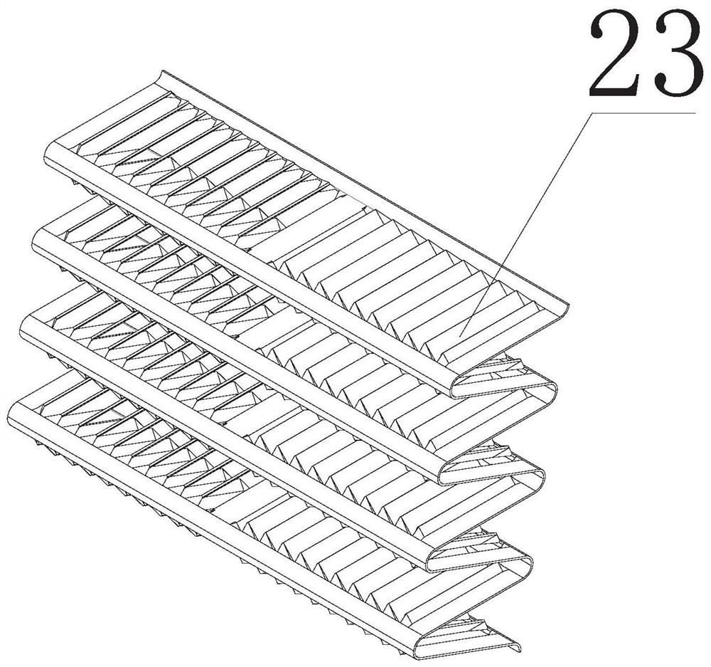
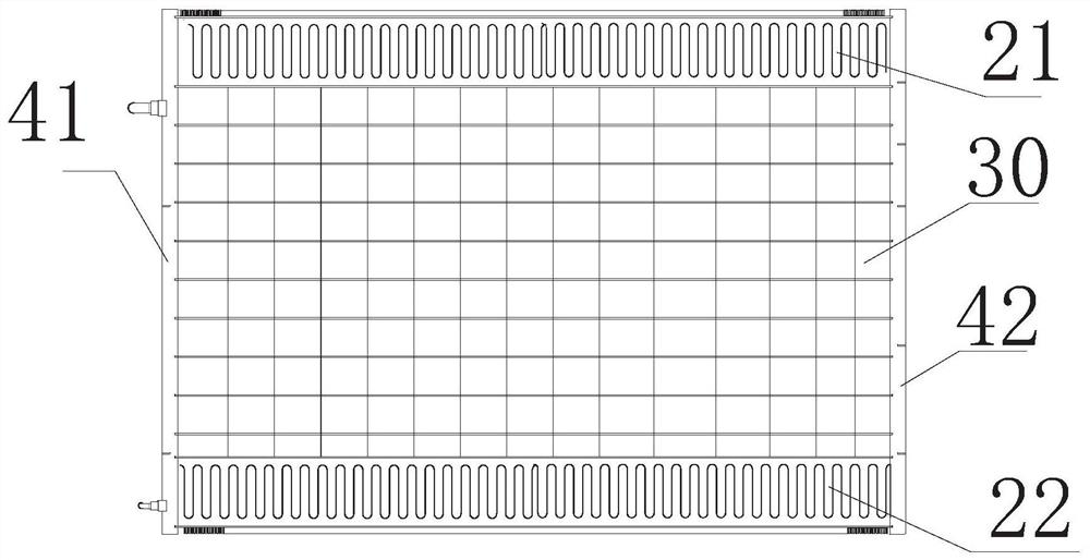
[0028] Please refer to Figure 1 to Figure 10 As shown, according to the embodiment of the present invention, the microchannel heat exchanger includes a plurality of flat tubes (not shown in the figure) for transporting refrigerant, the first heat dissipation part 20 and the second cooling part 20 arranged adjacently on the flat tubes. Two heat dissipation parts 30, the first heat dissipation part 20 has a plurality of corrugated microchannel heat dissipation fins 23, the second heat dissipation part 30 includes a plurality of plug-in fins, each of the plug-in fins The sheet has a flat tube groove for placing a flat tube, a part of the flat tube is embedded in the flat tube groove, and the other part of the flat tube is arranged between two adjacent microchannel cooling fins 23 In terms of heat dissipation, the he...


PUM


Abstract

The micro-channel heat exchanger of the present invention adopts two heat-dissipating parts at the same time in terms of heat dissipation, which can not only solve the drainage problem when the micro-channel is used as an evaporator, but also improve the heat exchange efficiency and reduce the cost. In addition, through the optimized design of the refrigeration system, the solution of the invention can also balance the problem of refrigerant charge balance during refrigerant cooling and heating.

Description

technical field [0001] The invention relates to the technical field of heat exchangers, in particular to a microchannel heat exchanger. Background technique [0002] Microchannel heat exchangers originated from the cooling of high-density electronic devices in the 1980s and the heat transfer problems of microelectromechanical systems that appeared in the 1990s. In 1981, Tuckerman and Pease proposed the concept of microchannel radiators; in 1985, Swife, Migliori and Wheatley developed a microchannel heat exchanger for two-fluid heat exchange. [0003] With the development of micro-manufacturing technology, people have been able to manufacture micro-scale heat exchangers composed of channels with a hydraulic diameter of 10-1000 μm. At present, conventional microchannel condensers used in single-cooling units have many advantages compared with traditional finned tube heat exchangers, such as higher heat exchange efficiency, lower wind resistance, lower refrigerant charge and l...

Claims


Application Information

Patent Timeline
Patent Type & Authority Patents(China)
IPC IPC(8): F25B39/00F28F17/00
CPCF25B39/00F28F17/005
Inventor 吴青昊江俊党聪聪
Owner ZHEJIANG DUNAN MASCH CO LTD
Why Eureka
Try Eureka