
Lens shift adaptive device and projection device

An adaptive and displacement technology, applied in the field of projection display, can solve the problems of stuck sliding shaft and sliding bracket, low machining accuracy, low roundness of shaft surface, etc., to improve yield, eliminate straightness deviation, and improve machining accuracy The effect of request reduction

Active Publication Date: 2021-05-11
APPOTRONICS CORP LTD
View PDF6 Cites 0 Cited by
  • Summary
  • Abstract
  • Description
  • Claims
  • Application Information

AI Technical Summary

Problems solved by technology

If the processing accuracy of the incoming material is not high, especially if the straightness deviation of the sliding shaft is too large, the parallelism deviation of the two sliding shafts is too large, and the roundness of the shaft surface is not high, it is easy to cause the sliding shaft and the sliding bracket to be stuck.

Method used


Image

  • Lens shift adaptive device and projection device
  • Lens shift adaptive device and projection device
  • Lens shift adaptive device and projection device

Examples


Embodiment Construction

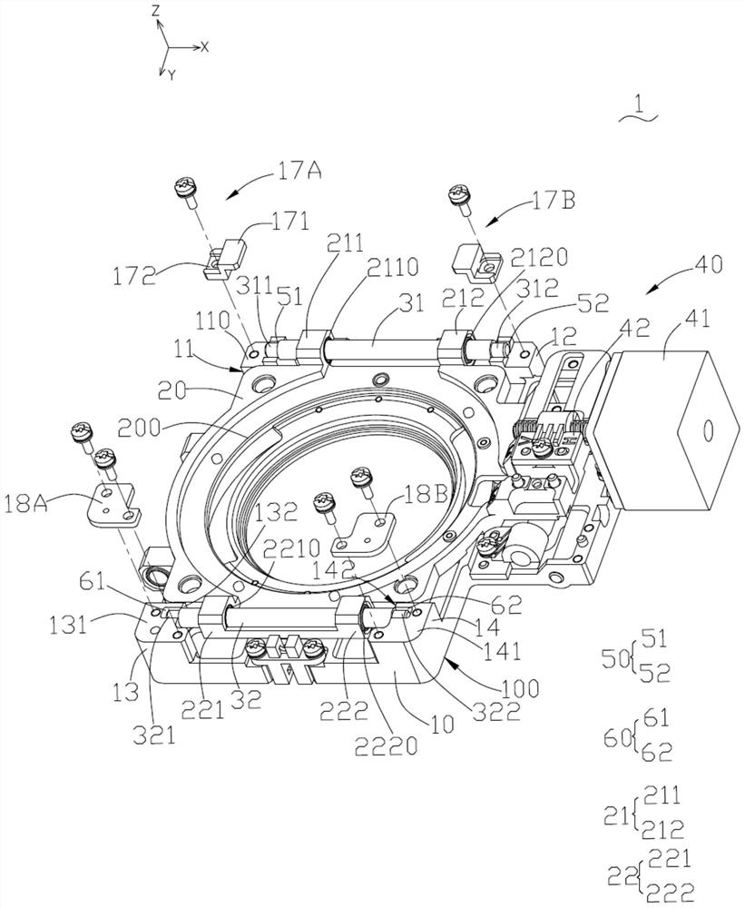
[0025] In order to enable those skilled in the art to better understand the solutions of the present invention, the technical solutions in the embodiments of the present invention will be clearly and completely described below in conjunction with the drawings in the embodiments of the present invention. Apparently, the described embodiments are only some of the embodiments of the present invention, but not all of them. Based on the embodiments of the present invention, all other embodiments obtained by those skilled in the art without creative efforts fall within the protection scope of the present invention.

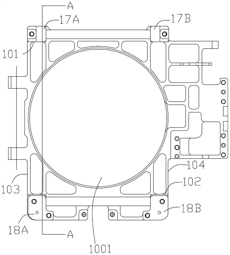
[0026] see Figure 1 to Figure 5 , the lens shift adaptive device 1 provided by the embodiment of the present invention includes a sliding shaft fixing base 10 , a sliding bracket 20 , a first sliding shaft 31 , a second sliding shaft 32 and a driving mechanism 40 .

[0027] The sliding shaft fixing base 10 includes a substantially square base 100, the base 100 has a f...


PUM


Abstract

The invention provides an adaptive lens displacement device, which comprises a sliding shaft fixing base, a sliding bracket, a first sliding shaft, a second sliding shaft and a driving mechanism. The opposite ends of the sliding shaft fixing base are respectively provided with a first groove and a second groove. Two grooves, so that when the sliding bracket slides in the X direction, with the help of the gap between the first groove and the first sliding shaft in the Z direction, and the gap between the second groove and the second sliding shaft in the Y direction, simultaneously The purpose of adjusting the displacement in the three directions of X, Y, and Z is to effectively absorb the processing deviation and assembly deviation between the components, so that the sliding bracket slides smoothly on the sliding shaft, and the adjustment effect is good. The present invention also provides a projection device including the lens displacement adaptive device.

Description

technical field [0001] The invention relates to the field of projection display, in particular to a lens displacement adaptive device and a projection device. Background technique [0002] Currently, projection devices have been widely used. During use, it is necessary to manually or automatically adjust the position of the lens to make the position of the lens reach a suitable position. For example, the common automatic centering function can make the lens automatically center. The lens is generally installed on the lens holder. The lens displacement device of the existing projection device generally adopts a method in which both ends of the sliding shaft are fixed, and the sliding bracket slides on the sliding shaft to adjust the lens displacement. If the processing accuracy of the incoming material is not high, especially if the straightness deviation of the sliding shaft is too large, the parallelism deviation of the two sliding shafts is too large, and the roundness o...

Claims


Application Information

Patent Timeline
Patent Type & Authority Patents(China)
IPC IPC(8): G03B21/14
CPCG03B21/142G02B7/00G03B21/14
Inventor 王云黄旻李屹
Owner APPOTRONICS CORP LTD
Learn More