Check patentability & draft patents in minutes with Patsnap Eureka AI!

source driver

A technology of source driver and operational amplifier, applied in the direction of instruments, static indicators, etc., can solve the problems of reduced equivalent impedance of switching switches, heavy output load, high power loss, etc., to reduce temperature, reduce power consumption, and improve rotation rate effect

Active Publication Date: 2021-06-08
RAYDIUM SEMICON
View PDF16 Cites 0 Cited by
  • Summary
  • Abstract
  • Description
  • Claims
  • Application Information

AI Technical Summary

Problems solved by technology

[0002] Generally speaking, as the size of the liquid crystal display panel becomes larger and larger, the output load of the driver IC of the display device becomes heavier and heavier, causing the driver IC of the display device to face the problem of overheating.
[0003] Specifically, in a traditional source driver, the highest potential of the control signal of the switching switch coupled to the output terminal of the operational amplifier of each channel is usually the same as the operating voltage of the operational amplifier, resulting in The equivalent impedance of the switching switch (that is, the on-resistance On-resistance) cannot be effectively reduced, making the slew rate of the operational amplifier poor
When the output current generated by the operational amplifier charging or discharging the load flows through a large on-resistance, it will generate a large power loss and cause the temperature of the driver IC to be too high, which needs to be overcome urgently

Method used


Image

  • source driver
  • source driver
  • source driver

Examples


Embodiment Construction

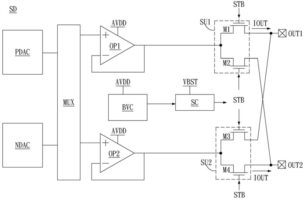
[0065] A specific embodiment according to the present invention is a source driver. In this embodiment, the source driver is arranged in the display device to drive the liquid crystal display panel.

[0066] Please refer to figure 1 , figure 1 A schematic diagram of the source driver in this embodiment. Such as figure 1 As shown, the source driver SD includes a first digital-to-analog converter PDAC, a second digital-to-analog converter NDAC, a multiplexer MUX, a first operational amplifier OP1, a second operational amplifier OP2, a first switching unit SU1, a second The switch unit SU2, the boost circuit BVC, the timing control circuit SC, the first output terminal OUT1 and the second output terminal OUT2 are exchanged.

[0067]The output terminals of the first digital-to-analog converter PDAC and the second digital-to-analog converter NDAC are respectively coupled to the two input terminals of the multiplexer MUX; the two output terminals of the multiplexer MUX are respe...


PUM


Abstract

The invention discloses a source driver. The source driver includes a first operational amplifier, a boost circuit and a first switch unit. The first operational amplifier is controlled by the control signal, and the highest potential of the control signal is the working voltage. The boost circuit is used for boosting the operating voltage to a boosted voltage and generating a switching switch control signal accordingly, wherein the highest potential of the switching switch control signal is the boosted voltage, and the boosted voltage is higher than the working voltage. The first switch unit is coupled to the first operational amplifier. When the first swap switch unit is controlled by the swap switch control signal to conduct, it has an on-resistance. If the first exchange switch unit has an original on-resistance when it is turned on by the control signal, the on-resistance is smaller than the original on-resistance.

Description

technical field [0001] The present invention relates to a display device, in particular to a source driver applied to a display device. Background technique [0002] Generally speaking, as the size of the liquid crystal display panel becomes larger and larger, the output load of the driving IC of the display device becomes heavier, which leads to the problem of overheating of the driving IC of the display device. [0003] Specifically, in a traditional source driver, the highest potential of the control signal of the switching switch coupled to the output terminal of the operational amplifier of each channel is usually the same as the operating voltage of the operational amplifier, resulting in The equivalent impedance of the switching switch (that is, the on-resistance On-resistance) cannot be effectively reduced, so that the slew rate of the operational amplifier is not good. When the output current generated by the operational amplifier charging or discharging the load f...

Claims


Application Information

Patent Timeline
Patent Type & Authority Patents(China)
IPC IPC(8): G09G3/36
CPCG09G3/3688
Inventor 黄智全吕骅洺
Owner RAYDIUM SEMICON
Features
  • R&D
  • Intellectual Property
  • Life Sciences
  • Materials
  • Tech Scout
  • Unparalleled Data Quality
  • Higher Quality Content
  • 60% Fewer Hallucinations
Learn More