
FC network time synchronization method based on complex network structure

A technology of network structure and network time, applied in multiplex communication, time division multiplexing system, electrical components and other directions, can solve the problems of FC network time synchronization, FC equipment priority cannot be transmitted, etc. Synchronization and dynamic fault tolerance

Active Publication Date: 2019-08-06
成都光航信科技有限公司
View PDF5 Cites 2 Cited by
  • Summary
  • Abstract
  • Description
  • Claims
  • Application Information

AI Technical Summary

Problems solved by technology

[0005] The purpose of the present invention is: the present invention provides a method for synchronizing the time of the FC network based on the complex network structure, which solves the problem that the priority of the existing FC equipment cannot be transferred and the time of the FC network of the complex network structure cannot be synchronized

Method used


Image

  • FC network time synchronization method based on complex network structure
  • FC network time synchronization method based on complex network structure
  • FC network time synchronization method based on complex network structure

Examples


Embodiment 1

[0070] The FC network includes multiple switching devices, which are connected to each other, and each switching device is connected to multiple FC devices, such as Figure 5 shown;

[0071] In this example, five switching devices constitute the Figure 7 The ring structure shown. The steps for time synchronization between device 1 and device 5 will be described in detail below, and the steps for time synchronization among other devices are the same. To facilitate the distinction between ID primitives and ID_RDY primitives in device 5 and device 1, specifically, ID primitives will be described as ID primitives 5 and ID primitives 1, and ID_RDY primitives will be described as ID_RDY primitives respectively. Language 5 and ID_RDY primitive 1; among them, ID primitive 5 represents the primitive containing the device ID of device 5, ID primitive 1 represents the primitive containing the device ID of device 1, and the device ID of device 1 is 0x01, and device 2 The device ID of ...

Embodiment 2

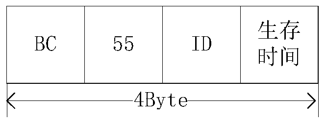
[0091] The time-to-live is set in the ID primitive of the device in this application, and the time-to-live can improve the fault tolerance of the method; the time-to-live set by each device is 0xff, and the time-to-live is subtracted by 1 each time the ID primitive is sent. If the adjacent device fails, the survival time in the register will not be updated, and the survival time will be decremented to 0x00. At this time, the device will re-initiate synchronization, and the main clock ID value in the register will be configured as the local device ID. Configured as 0xff.

[0092] exist Figure 8 In the linear structure, the device ID of device 1 is 0x01, the device ID of device 2 is 0x02, the ID of device 3 is 0x03, the ID of device 4 is 0x04, and the initial survival time is 0xff. After the synchronization is completed, the master clock ID values ​​of the devices are all updated to the device IDs with the highest priority, that is, the master clock ID values ​​of devices 1 to...


PUM


Abstract

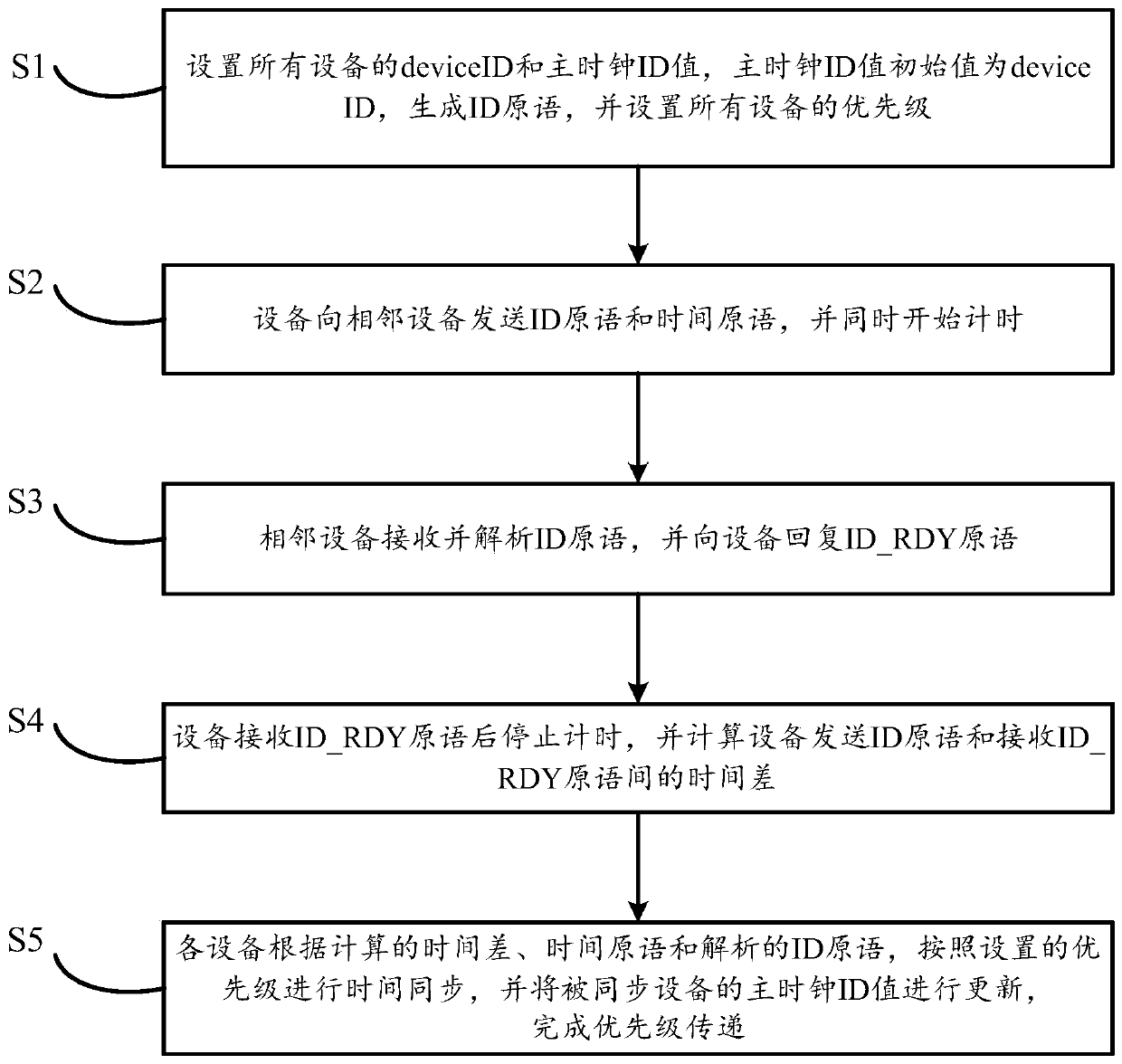
The invention discloses an FC network time synchronization method based on a complex network structure, and relates to the field of FC network time synchronization methods. The method comprises the steps that 1, device IDs and master clock ID values of all devices are set, the initial values are the device IDs, ID primitives are generated, and the priorities of all the devices are set; 2, the device sends an ID primitive and a time primitive to an adjacent device, and timing is started at the same time; step 3, the adjacent device receives and analyzes the ID primitive, and replies the ID _ RDY primitive to the device; 4, after receiving the ID _ RDY primitive sent by the adjacent device, the device stops timing and calculates the time difference; step 5, the devices are synchronized according to the set priorities and the master clock ID values of the synchronized devices are updated to complete priority transmission; according to the method, the problem that FC network time of a complex network structure cannot be synchronized due to the fact that priority of existing FC equipment cannot be transmitted is solved, and the effects of achieving priority transmission and time synchronization of all FC equipment are achieved.

Description

technical field [0001] The invention relates to the field of FC network time synchronization methods, in particular to a method for FC network time synchronization based on complex network structures. Background technique [0002] FC is a high-speed serial transmission bus proposed by the American Standardization Committee. Due to its dual advantages of channel and network, it has the advantages of high bandwidth, high reliability, and resistance to electromagnetic interference. It can realize stable and reliable optical fiber connection, which is conducive to the construction of large data Transmission and communication networks. [0003] At present, the FC protocol has been widely used in various industries, especially in the field of avionics, which requires very high stability and reliability. Adding a time-triggered mechanism to the FC protocol to meet the requirements of strong real-time performance is a must in the field of avionics or vehicles. inevitable trend. Th...

Claims


Application Information

Patent Timeline
Patent Type & Authority Applications(China)
IPC IPC(8): H04J3/06
CPCH04J3/0667H04J3/0682
Inventor 陈昌祯涂晓东张创张金国谢军
Owner 成都光航信科技有限公司
Learn More