
Magnetic strip for electromagnetic oven

A technology of induction cooker and magnetic strip, applied in electric/magnetic/electromagnetic heating, electric heating devices, electrical components, etc., can solve the problems of reducing the service life of magnetic strips, uneven density, thickness, low heating efficiency at the connection, etc. Service life, reduce the probability of cracking, not easy to deform

Inactive Publication Date: 2019-08-06
徐州祥顺电子科技有限公司
View PDF0 Cites 0 Cited by
  • Summary
  • Abstract
  • Description
  • Claims
  • Application Information

AI Technical Summary

Problems solved by technology

This traditional U-shaped magnetic strip has a relatively small magnetic flux area at the connection, resulting in low heating efficiency at the connection
In addition, during the sintering process of the magnetic strip, due to its uneven density and thickness, the deformation of the magnetic strip will occur, which will reduce the service life of the magnetic strip

Method used


Image

  • Magnetic strip for electromagnetic oven

Examples


Embodiment Construction

[0012] The present invention will be further described below in conjunction with accompanying drawing.

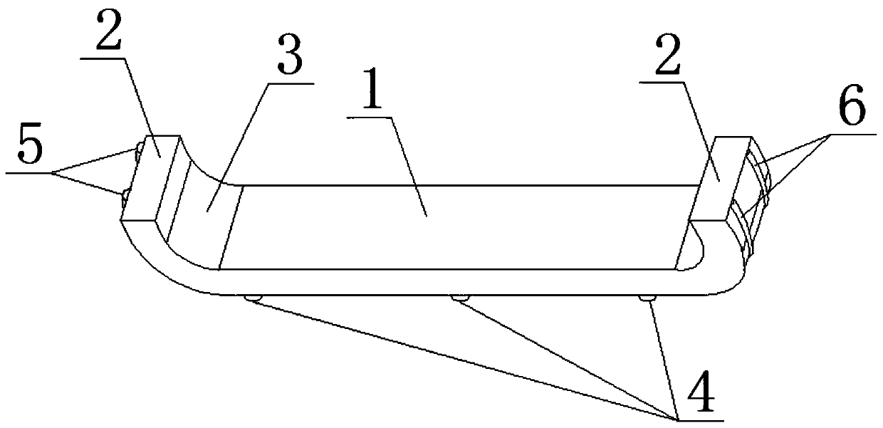
[0013] Such as figure 1 As shown, a magnetic strip for an induction cooker includes a horizontal part 1, two vertical parts 2, two arc-shaped transition parts 3, two reinforcing ribs B5 and two reinforcing discs C, and the two vertical parts 2 are respectively Two transition parts 3 are connected to the two ends of the horizontal part 1, the inner surface of the transition part 3 is smoothly transitioned with the inner surface of the horizontal part 1 and the inner surface of the vertical part 2 respectively, and the outer surface of the transition part 3 is connected with the horizontal part respectively. The outer surface of 1 and the outer surface of the vertical part 2 are smoothly transitioned; the outer surface of the horizontal part 1 is evenly connected with three reinforcing ribs A4 along its length direction;

[0014] Two reinforcing ribs B5 are evenly connected ...


PUM


Abstract

The invention relates to a magnetic strip for an electromagnetic oven, which is characterized in that two vertical parts are respectively connected with two ends of a horizontal part through two transition parts, the inner surface of each transition part is in smooth transition with the inner surface of the horizontal part and the inner surface of the corresponding vertical part, and the outer surface of each transition part is in smooth transition with the outer surface of the horizontal part and the outer surface of the corresponding vertical part; the outer surface of the horizontal part isuniformly connected with three reinforcing ribs A along the length direction; two reinforcing ribs B are uniformly connected on the outer surface of the left vertical part along the width direction of the horizontal part, and one end of each reinforcing rib B starts at the upper end of the vertical part, the other end extends through the vertical part and the transition part and is connected withthe reinforcing rib A at the left side; two reinforcing discs C are uniformly connected on the outer surface of the right vertical part along the width direction of the horizontal part, one end of each reinforcing rib C starts at the upper end of the vertical part, and the other end extends through the vertical part and the transition part and is connected with the reinforcing rib A at the rightside. The magnetic strip is large in magnetic flux area at the junction of the horizontal part and the vertical part, high in heating efficiency and not easy to deform.

Description

technical field [0001] The invention relates to, in particular to a magnetic strip for an electromagnetic cooker. Background technique [0002] The coil disk of the induction cooker includes a bracket, a coil built in the bracket, and a magnetic strip arranged outside the bracket. The main function of the magnetic strip is to reduce the magnetic resistance, improve the efficiency and power of the coil disk, and guide the direction of the magnetic force line. Conventional magnetic strips are generally bar-shaped or U-shaped, wherein a U-shaped magnetic strip includes a horizontal portion and a vertical vertical portion connected to an end of the horizontal portion, and the horizontal portion and the vertical portion are integrally formed. This traditional U-shaped magnetic strip has a relatively small magnetic flux area at the connection, resulting in low heating efficiency at the connection. In addition, during the sintering process of the magnetic strip, due to its uneven ...

Claims


Application Information

Patent Timeline
Patent Type & Authority Applications(China)
IPC IPC(8): H05B6/36H05B6/12H05B1/02
CPCH05B1/0258H05B6/1245H05B6/36Y02B40/00
Inventor 朱国梁
Owner 徐州祥顺电子科技有限公司
Learn More