
Printhead having a temperature-control device

A temperature control device and temperature control technology, applied in viscosity control, valve device, inking device, etc., can solve the problems of high viscosity of coating medium, low viscosity of coating medium, unfavorable continuous production, etc., and achieve high on/off frequency Effect

Active Publication Date: 2019-08-06
DUERR SYST GMBH
View PDF11 Cites 3 Cited by
  • Summary
  • Abstract
  • Description
  • Claims
  • Application Information

AI Technical Summary

Problems solved by technology

A high on / off frequency or a permanent opening can lead, for example, to a high degree of heat and thus to a low viscosity of the coating medium, whereas a low frequency or only brief opening can lead to less heat and thus to a higher viscosity of the coating medium
Changes in this situation are not good for serial production

Method used


Image

  • Printhead having a temperature-control device
  • Printhead having a temperature-control device
  • Printhead having a temperature-control device

Examples


Embodiment Construction

[0082] Partially corresponding preferred embodiments of the invention are described with reference to the figures, wherein similar or identical parts bear the same reference numerals, and for the sake of explanation, reference is also made to the description of other embodiments or figures to avoid repetition.

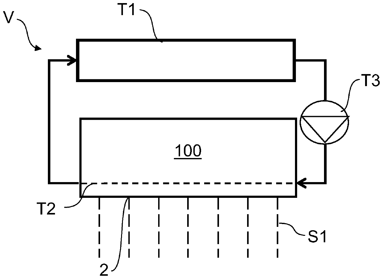
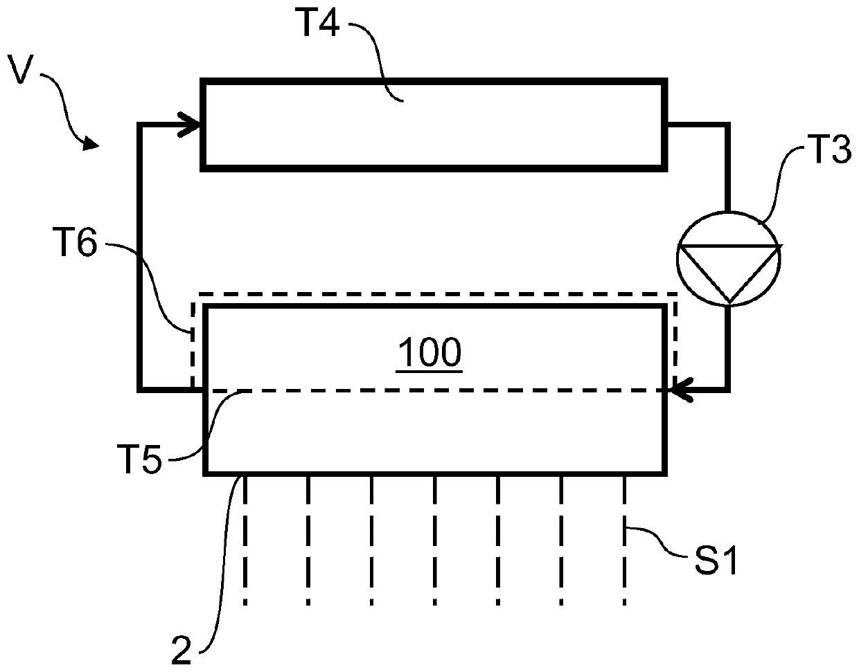
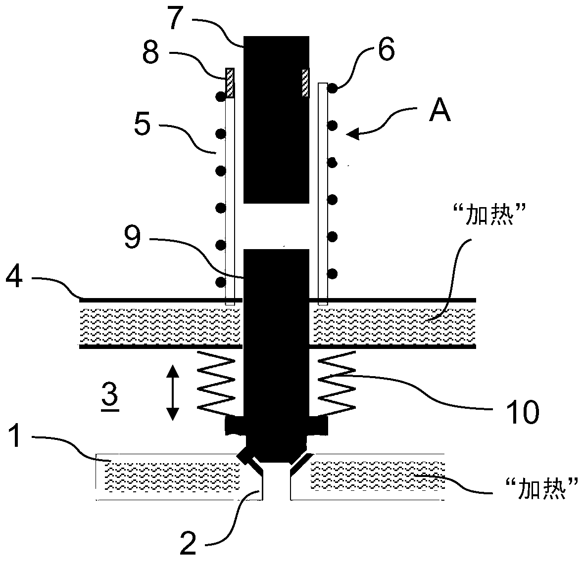
[0083] figure 1 A schematic diagram of an application device V having a printing head 100 according to an embodiment of the present invention is shown, wherein, image 3 A schematic / detailed view of a portion of printhead 100 is shown. The application device V, especially the jet printing head 100 is hereinafter combined figure 1 and 3 to describe.

[0084] The application device V is used for applying a coating medium to components, in particular for applying paint to motor vehicle body parts. For this purpose, the application device V includes in particular a printing head 100 for the continuous, continuous and substantially atomized and spray-free application of...


PUM

PropertyMeasurementUnit
Viscosityaaaaaaaaaa
Viscosityaaaaaaaaaa

Abstract

The invention relates to an application device (V) for applying an application agent to a component, preferably for applying a coat to a motor-vehicle body component. The application device (V) comprises a printhead (100) for preferably serially and / or continuously applying the application agent, wherein the printhead (100) has: a nozzle plate (1), at least one nozzle (2) in the nozzle plate (1) for dispensing the application agent, at least one valve element (9) movable relative to the nozzle plate (1) for controlling the dispensing of the application agent by means of the at least one nozzle(2), wherein the at least one movable valve element (9) closes the at least one nozzle (2) in a closed position and opens the at least one nozzle in an open position, and at least one drive (A) for moving the at least one valve element (9). The application device (V) is characterized in particular in that the application device comprises at least one temperature-control device (T1-T8) for reducing heating of the at least one drive (A) during the application of the application agent.

Description

technical field [0001] The invention relates to an application device for applying a coating medium to components, preferably for applying paint to motor vehicle body components, comprising a printing head for preferably serially and / or Or apply the coating medium without overspray. Background technique [0002] Atomizers (such as rotary atomizers, air mixing atomizers, airless atomizers, etc.) are commonly used as application equipment for the continuous spraying of automotive body parts, but these have limited application efficiency The disadvantage is that only a part of the applied paint is deposited on the part to be coated, while the rest of the applied paint has to be disposed of as so-called overspray. [0003] With regard to the general prior art, reference is first made to DE 20 2013 101 134 U1, DE 10 2010 019 612 A1 and DE 197 43 804 A1. [0004] US 9,108,424 B2 discloses a drop-on-demand valve jet printer whose working principle is based on the use of electric ...

Claims


Application Information

Patent Timeline
IPC IPC(8): B05B1/24F16K49/00G05D24/00B41J29/377B05B1/30B05B13/04B05B12/10
CPCB05B1/24B05B1/3053B05B12/10B05B13/0452F16K49/005F16K31/004B05B1/02B05B12/149B05C5/0225B05C5/001B41J3/4073B05B13/0431B05C5/0291B05C11/1042B25J11/0075B41J2/06B41J2202/08
Inventor H-G·弗里茨B·沃尔M·克莱纳M·布贝科T·贝尔F·赫勒S·索茨尼
Owner DUERR SYST GMBH
Learn More