Physiotherapy device applicable to patient suffering from rheumatism

A technology for rheumatism and patients, applied in the field of medical devices, can solve the problems of lack of continuity in massage, poor drug absorption effect, and increase the labor intensity of personnel, so as to reduce labor intensity, achieve absorption effect, and facilitate use.

Inactive Publication Date: 2019-08-09
QINGDAO HISER MEDICAL CENT
View PDF5 Cites 11 Cited by
  • Summary
  • Abstract
  • Description
  • Claims
  • Application Information

AI Technical Summary

Problems solved by technology

[0004] The purpose of the present invention is to provide a physical therapy device suitable for rheumatism patients in order to solve the problems of poor drug absorption, lack of continuity in massage, and increased fatigue intensity of personnel.

Method used


Image

  • Physiotherapy device applicable to patient suffering from rheumatism
  • Physiotherapy device applicable to patient suffering from rheumatism
  • Physiotherapy device applicable to patient suffering from rheumatism

Examples


Embodiment 1

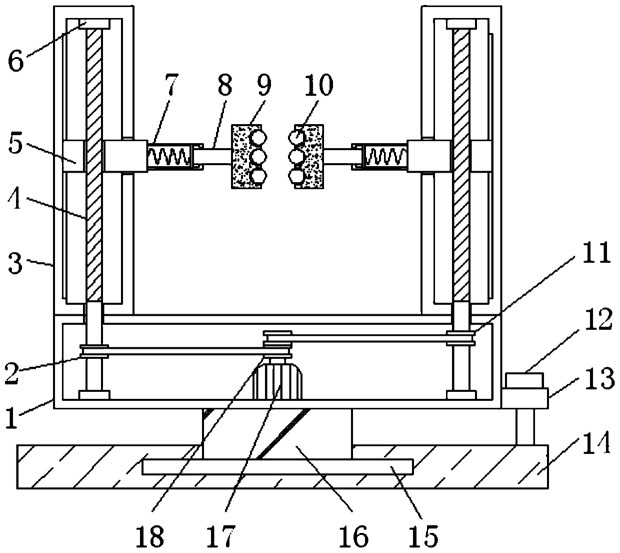
[0025] Embodiment one, with reference to figure 1 , a physical therapy device suitable for patients with rheumatism, comprising a pedal box 1, the top of the pedal box 1 is correspondingly welded with two positioning columns 3 at the edge, and the corresponding surfaces of the two positioning columns 3 are provided with movable grooves 31, the two The interior of each positioning post 3 is provided with two threaded rods 4 along the vertical center line, and one end of the two threaded rods 4 extends into the pedal box 1, and the two ends of the two threaded rods 4 are sleeved with two bearings Cover 6, wherein, the two bearing sleeves 6 at the top are respectively welded with the inner walls of the two positioning columns 3, and the other two bearing sleeves 6 are welded with the inner wall of the pedal box 1, between the bearing sleeves 6 and the two threaded rods 4 Bearings are provided to facilitate the rotation of the threaded rod 4. Two sliders 5 are slidably embedded in...

Embodiment 2

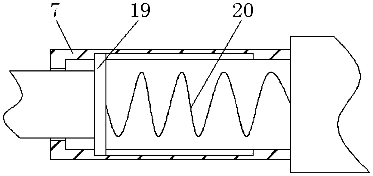
[0026] Embodiment two, refer to figure 1 , 2 , 4 and 5, the top center of the inner wall of the pedal box 1 is detachably connected with a drive motor 17, the model of the drive motor 17 is YE2-2P, the drive motor 17 can rotate positively and negatively, and the top of the drive motor 17 is connected through the rotating shaft There are double sheave 18. The outer walls of the two threaded rods 4 are located in the pedal box 1 and are respectively sleeved with a first sheave 2 and a second sheave 11, and both the first sheave 2 and the second sheave 11 are rotatably connected to the double sheave 18 by a belt. , so that the same direction rotation of the two threaded rods 4 is realized by the rotation of the double sheave 18. One end of the two position-limiting tubes 7 away from the two slide blocks 5 is welded with two slide bars 8, and the end of the slide bar 8 located in the two position-limiting tubes 7 is welded with two pressing plates 19, and the other side of the t...

Embodiment 3

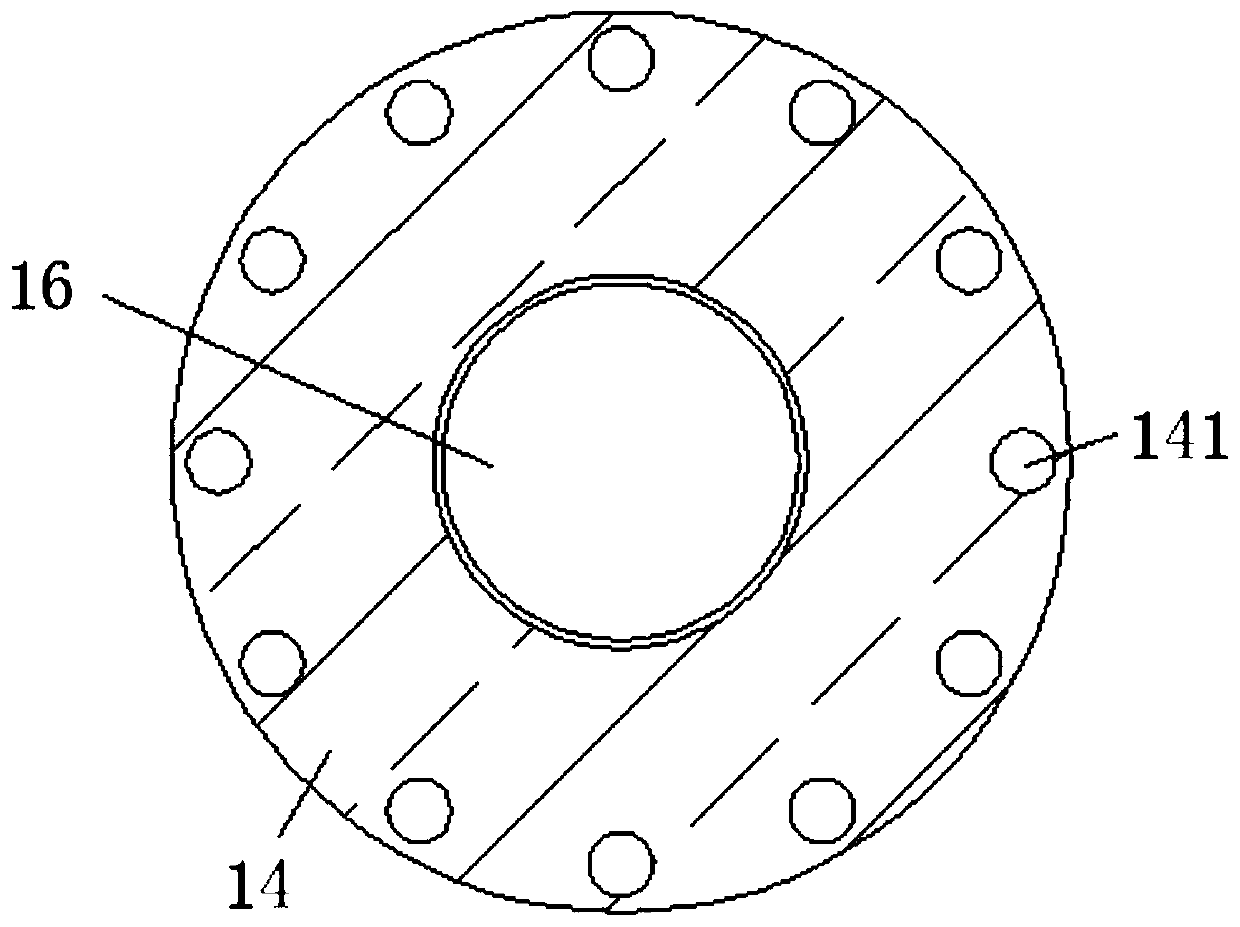
[0027] Embodiment three, refer to figure 1 and 3 , the bottom of the pedal box 1 is provided with a base 14, the inner center of the base 14 is rotated and embedded with a rotating block 15, and the top center of the rotating block 15 is welded with a connecting rod 16, and the other end of the connecting rod 16 is connected to the pedal box 1 Welding, so that the rotation of the pedal box 1 is realized by rotating the rotating block 15 and the connecting rod 16 in the base 14 . , one side of the pedal box 1 is welded with a fixing block 13 , and the fixing block 13 is threaded with a screw 12 along the vertical direction, and the screw 12 extends into the pedal box 1 . The top of the pedal box 1 is evenly provided with a plurality of nail holes 141, and the connection line of the plurality of nail holes 141 is a ring structure, so that the screw 12 can be inserted into one of the nail holes 141 to realize the fixing of the pedal box 1. The device can be screwed Move the scr...


PUM


Abstract

The invention discloses a physiotherapy device applicable to a patient suffering from rheumatism. The physiotherapy device comprises a pedal box, two positioning columns are correspondingly welded tothe portions, located at the edges, of the top of the pedal box, and movement grooves are formed in the corresponding surfaces of the two positioning columns; two threaded rods penetrate into the twopositioning columns along vertical central lines. The physiotherapy device is driven by a driving motor and can be used by the patient at any time without carrying out continuous operation by a worker, the labor intensity of medical staff can be effectively reduced, and convenience is provided for use. Two half-ring clamping blocks can be moved up and down on the legs, the legs can be massaged byrolling balls, and continuous massage can be achieved. A screw can be detached from a screw hole by screwing so that the pedal box can be rotated; the positions of the two half-ring clamping blocks onthe legs are adjusted, the effect of massaging the peripheries of the legs can be achieved, and the absorption effect of tissue on drugs can be better achieved.

Description

technical field [0001] The invention belongs to the technical field of medical devices, in particular to a physiotherapy device suitable for rheumatism patients. Background technique [0002] Rheumatism is a group of diseases mainly invading joints, bones, muscles, blood vessels and related soft or connective tissues, most of which are autoimmune diseases. The onset is mostly hidden and slow, the course of the disease is long, and most of them have genetic predisposition. In clinical practice, for rheumatoid arthritis, it is necessary to combine anti-inflammatory painkillers with exercise, so as to remove inflammation, relieve the condition, control the deterioration of joint inflammation, and maintain the motor function of the joints as much as possible. Deformities and lesions are placed on the joints. In addition, the medical staff will massage the patient's legs, which can be beneficial to the condition and the patient's recovery. [0003] The traditional physical ther...

Claims


Application Information

Patent Timeline
Patent Type & Authority Applications(China)
IPC IPC(8): A61H15/02A61M37/00
CPCA61H15/0078A61H15/02A61H2015/005A61H2201/1207A61H2205/106A61H2205/108A61M37/00A61M2037/0007
Inventor 宋彩霞
Owner QINGDAO HISER MEDICAL CENT
Why Eureka
Try Eureka