Automatic laser marking equipment

A laser marking equipment and equipment technology, applied in laser welding equipment, welding equipment, metal processing equipment, etc., can solve the problem of low blanking efficiency, achieve the effect of improving blanking efficiency and overall work efficiency

Pending Publication Date: 2019-08-09
深圳市艾雷激光科技有限公司
View PDF0 Cites 4 Cited by
  • Summary
  • Abstract
  • Description
  • Claims
  • Application Information

AI Technical Summary

Problems solved by technology

[0004] The purpose of the present invention is to provide an automatic laser marking equipment, which aims to solve the technical pr

Method used


Image

  • Automatic laser marking equipment
  • Automatic laser marking equipment
  • Automatic laser marking equipment

Examples


Example Embodiment

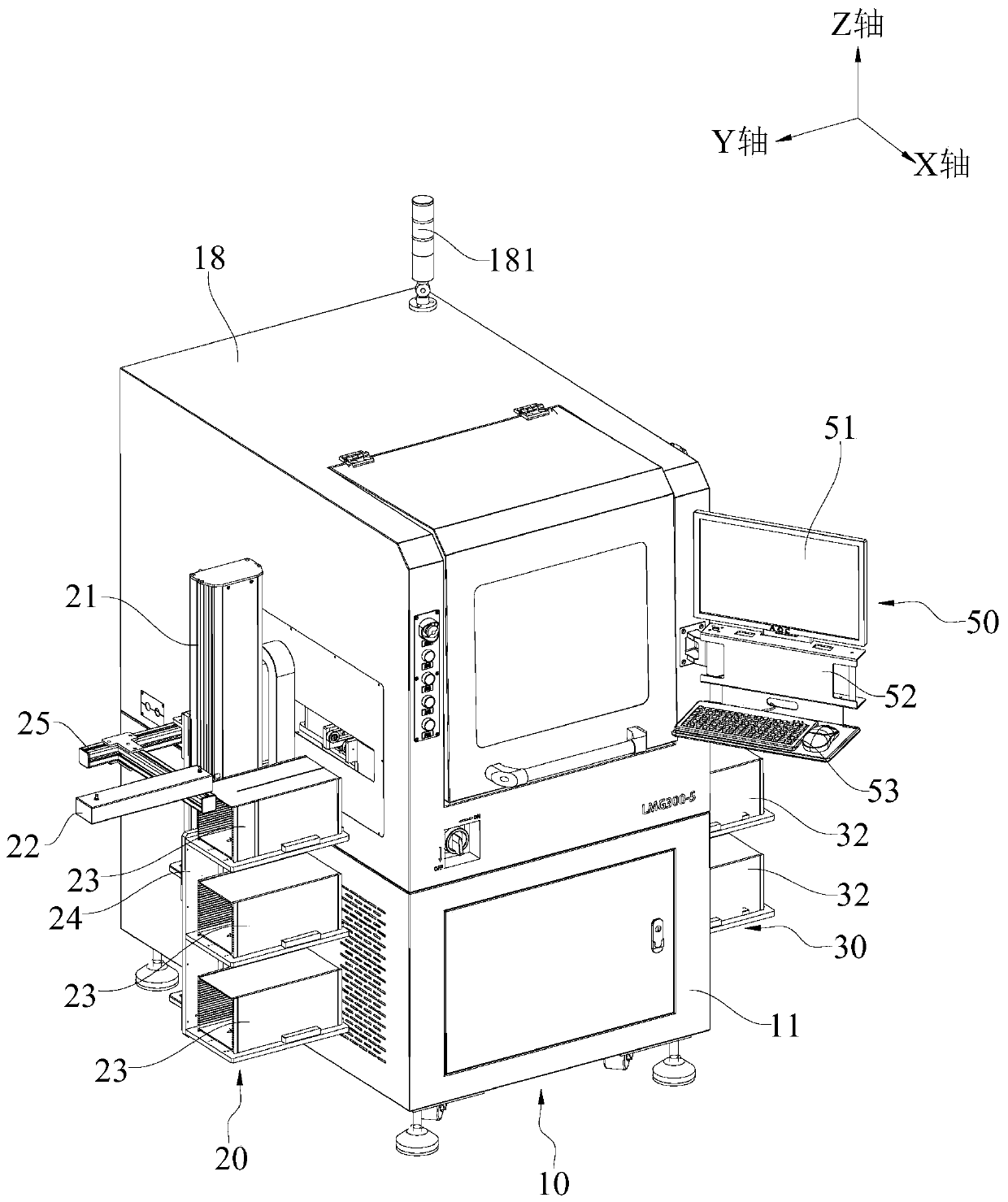
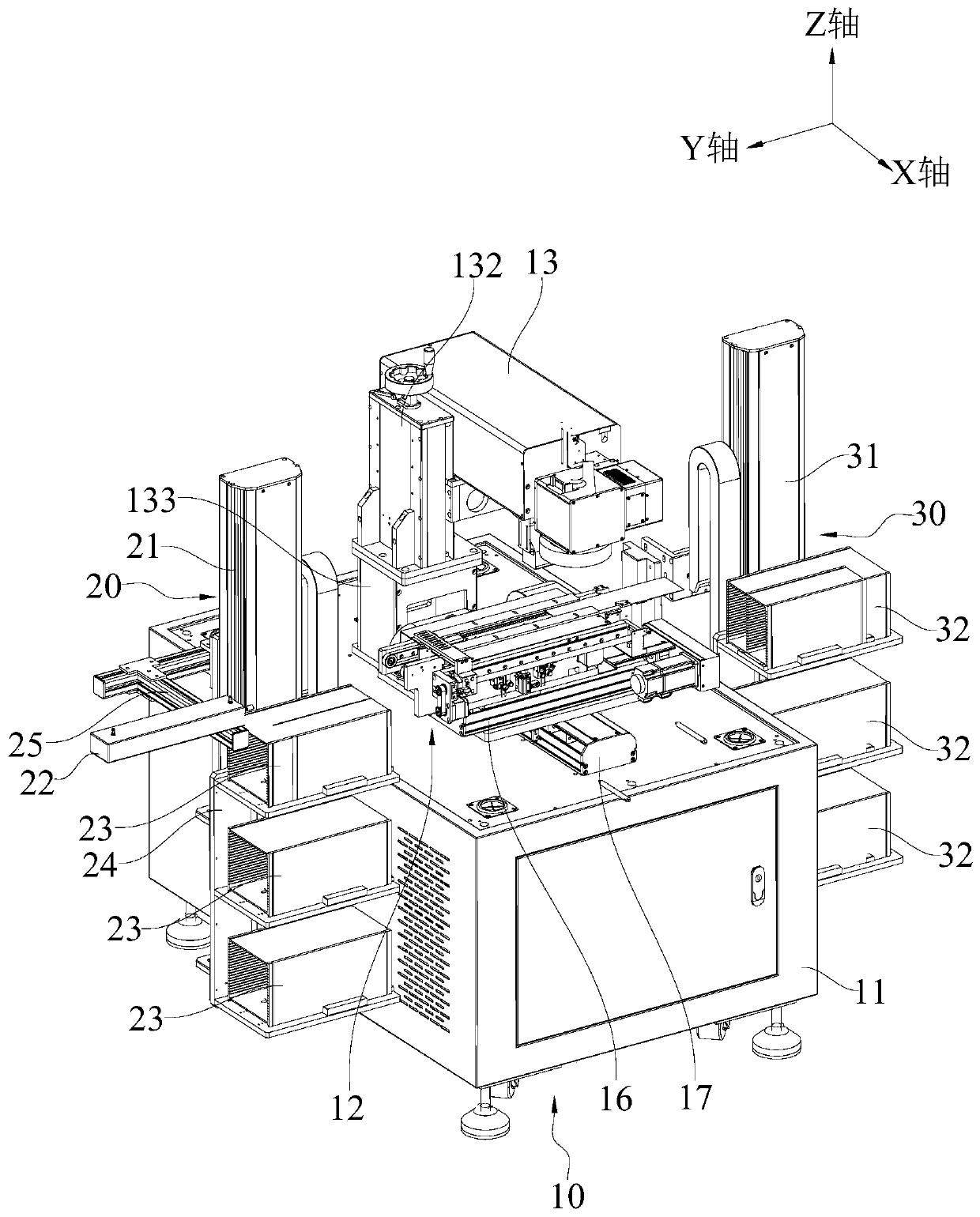
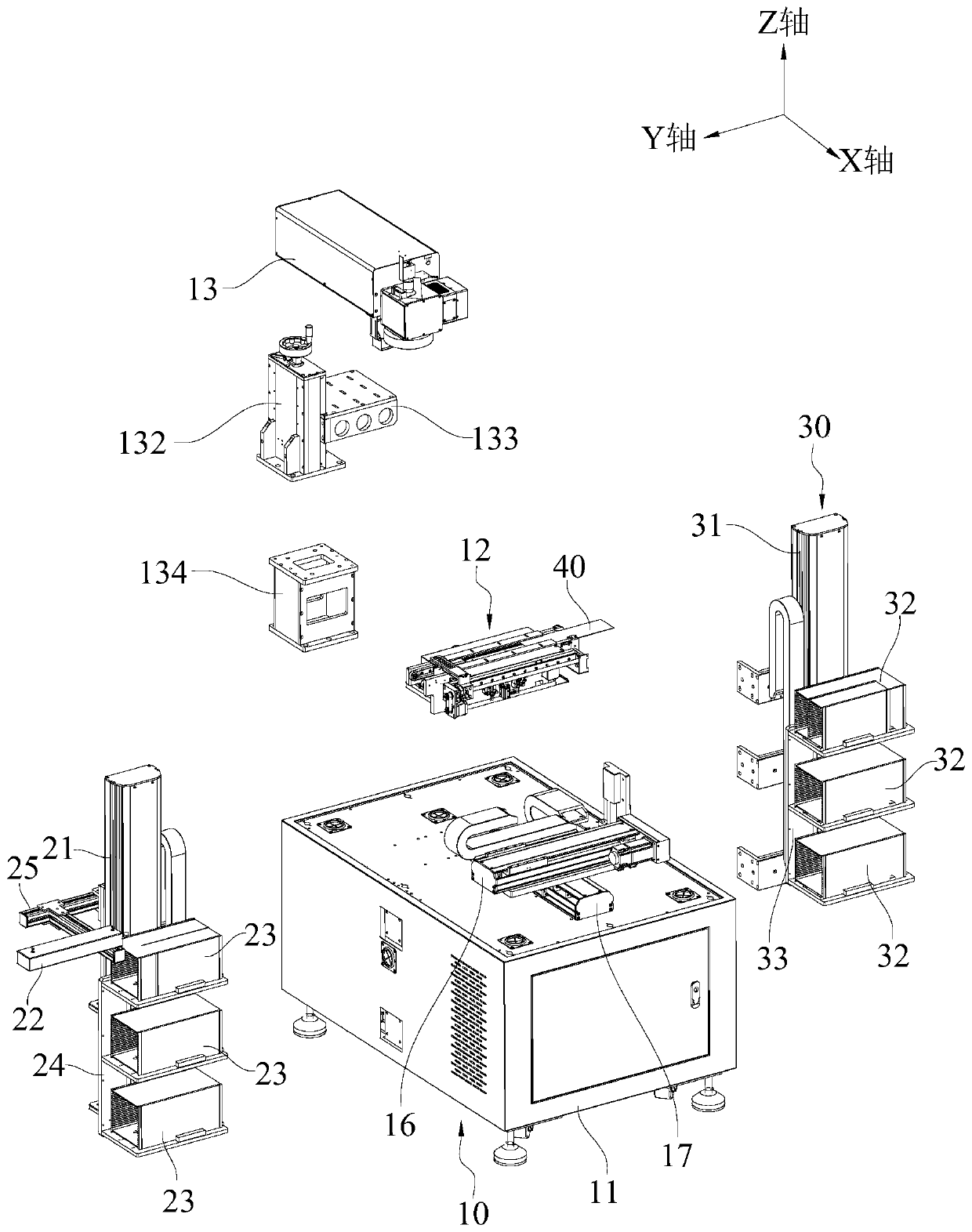
[0041] The embodiments of the present invention are described in detail below. Examples of the embodiments are shown in the accompanying drawings, in which the same or similar reference numerals indicate the same or similar elements or elements with the same or similar functions. The following is attached by reference Figure 1~6 The described embodiments are exemplary and are intended to explain the present invention, but should not be construed as limiting the present invention.

[0042] In the description of the present invention, it should be understood that the terms "length", "width", "upper", "lower", "front", "rear", "left", "right", "vertical", The orientation or positional relationship indicated by "horizontal", "top", "bottom", "inner", "outer", etc. is based on the orientation or positional relationship shown in the drawings, and is only for the convenience of describing the present invention and simplifying the description, not It indicates or implies that the pointe...


PUM


Abstract

The invention belongs to the technical field of laser marking equipment, and in particular, relates to automatic laser marking equipment. The equipment comprises an equipment main body, a loading device and an unloading device; the equipment main body comprises a frame, a conveying device and a laser; the conveying device comprises a device main body and a pushing mechanism; a laser head of the laser is arranged corresponding to a conveying path of the device main body; the device main body is provided with an input side and an output side oppositely arranged; the loading module is arranged corresponding to the input side, and is used for conveying marked objects to the device main body; the unloading device is arranged corresponding to the output side; and the pushing mechanism is arranged on the device main body, and is used for pushing the laser-marked objects from the output side of the device main body to the unloading device. The pushing mechanism can achieve an excellent joiningeffect between the conveying device and the unloading device; and the marked objects can be quickly pushed to the unloading device by the pushing mechanism, so that the unloading efficiency of the marked objects is improved, and the overall working efficiency of the automatic laser marking equipment is improved.

Description

technical field [0001] The invention belongs to the technical field of laser marking equipment, in particular to an automatic laser marking equipment. Background technique [0002] Electronic devices need to be marked with model, category and other relevant codes on their surface before leaving the factory. In the electronic device marking process, the electronic device is usually placed on a workbench, and the surface of the electronic device is marked by a marking device. [0003] In the prior art, marking objects such as electronic products need to be transported to the main body of the equipment through the loading equipment, and then moved to the unloading equipment after the laser marking process is completed. In actual operation, there is still no seamless connection between the main body of the equipment and the blanking equipment, which makes the blanking efficiency of marking objects such as electronic products relatively low relative to the main body of the equip...

Claims


Application Information

Patent Timeline
IPC IPC(8): B23K26/362B23K26/70
CPCB23K26/362B23K26/702
Inventor 蒋丽君张洋
Owner 深圳市艾雷激光科技有限公司
Why Eureka
Try Eureka