Unpowered automatic siphon water supply and drainage system

A water supply and drainage, automatic technology, applied in the direction of waterway systems, siphons, drainage structures, etc., can solve the problem of high comprehensive cost, and achieve the effect of high degree of automation and wide application range

Inactive Publication Date: 2019-08-09
XIAMEN CITY YIJING ENVIRONMENT ENG CO LTD
View PDF9 Cites 18 Cited by
  • Summary
  • Abstract
  • Description
  • Claims
  • Application Information

AI Technical Summary

Problems solved by technology

Due to the generation of power consumption cost and management and maintenance cost

Method used


Image

  • Unpowered automatic siphon water supply and drainage system
  • Unpowered automatic siphon water supply and drainage system
  • Unpowered automatic siphon water supply and drainage system

Examples


Embodiment 1

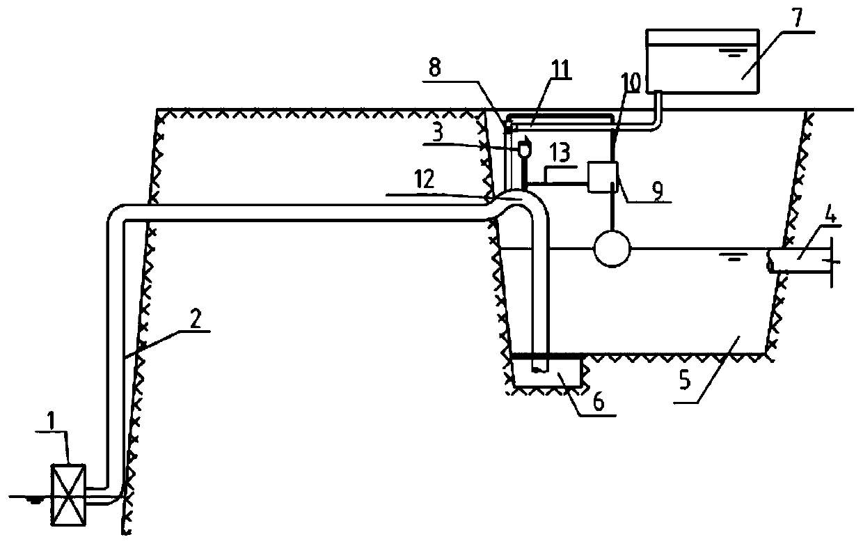
[0063] as attached figure 1 , this embodiment belongs to a typical siphon system, and it is used in the scene where the highest water level of the pool 5 in the low area is lower than the top of the siphon tube 2. Of course, the height difference between the lowest water level of the pool 5 in the low area and the top of the siphon tube is less than the atmospheric pressure can withstand The maximum water pressure height difference is also a necessary condition, and the working process of the system is:

[0064] First, divide the water into different areas, collect and transmit the water source in the high area through a separate pipe network, and realize the water injection process without additional power. As the water inlet pipe 4 of the low area pool 5 continuously injects water into the low area pool 5, the water level of the low area pool 5 gradually rises , when the water level reaches the threshold value, the siphon pilot valve 9 drives the hydraulic control valve 8 to...

Embodiment 2

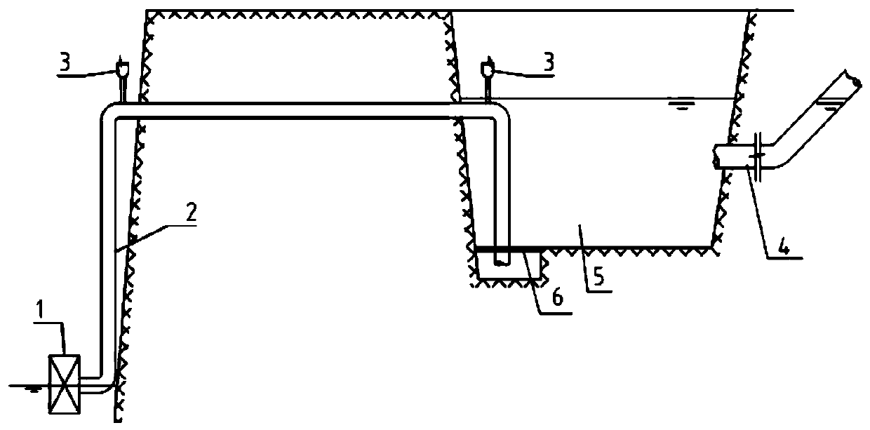
[0071] The application scenario of this embodiment is: the highest water level of the low area pool 5 is often higher than the pipe top of the siphon 2, in essence, the highest water level of the low area pool 5 can meet the water level requirements of the siphon 2, so the high The district water source 7 and the water source of the low district pool 5 are combined into one, so some water injection-related facilities in Embodiment 1 can be dismantled in this example.

[0072] as attached figure 2 , Only keep the automatic pressure relief valve 1, siphon pipe 2, exhaust check valve 3, low area pool water inlet pipe 4, low area pool 5 and suction pool with filter screen 6, the automatic siphon process can be realized. It should be noted that when there is no need for water volume adjustment and the water quality does not affect the system operation, even the water inlet pipe 4 of the low area pool, the low area pool 5 and the suction well 6 with a filter can also be cancelled, ...

Embodiment 3

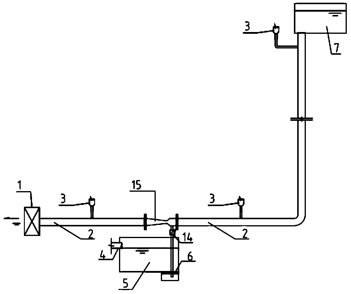
[0075] as attached image 3 , the application scenario of this embodiment is: the elevation of the highest water level of the pool 5 in the low area is lower than the elevation of the automatic pressure relief valve 1 and the height of the pool at the high level is sufficient. The system is connected to the siphon pipe 2 by the automatic pressure relief valve 1, and a water ejector 15 is arranged on the siphon pipe 2, and the water suction port of the water ejector 15 is connected with a branch pipe of the siphon pipe 2 to the suction well 6 with a filter screen at the bottom of the pool 5 in the low area. Also need to establish a check valve 14 on the branch pipe.

[0076]Similar to Embodiment 1 and Embodiment 2 above, several exhaust check valves 3 are provided on the main pipe of the siphon pipe 2 , and the water inlet end of the main pipe of the siphon pipe 2 is connected to the water source 7 in the high area. The difference is that the water source 7 in the high area sh...


PUM


Abstract

The invention relates to an unpowered automatic siphon water supply and drainage system. The unpowered automatic siphon water supply and drainage system comprises five parts of a low-area water source, a siphon pipe, siphon water flow control equipment, an exhaust one-way valve and water injection equipment, wherein the low-area water source comprises a water inlet pipe, a low-area water pool anda suction well with a filter screen; the siphon water flow control equipment is an automatic pressure relief valve; and the water injection equipment comprises a water injection pipe, a liquid level control valve, a siphon pilot valve, a water seal elbow pipe, a high-area water source, a hydraulic pipe and a pneumatic pipe, wherein the liquid level control valve is controlled by the siphon pilot valve, the liquid level control valve and the siphon pilot valve are connected by the hydraulic pipe, the hydraulic pipe is provided with a time-lapse self-closing valve, and the siphon pilot valve isarranged above the liquid level of the lower-area water pool. According to the unpowered automatic siphon water supply and drainage system, the elevation difference of all water inlet and outlet can be realized, an unpowered automatic siphon water supply and drainage function of occasions where the water level of some water sources is lower than water outlets can be realized, and the unpowered automatic siphon water supply and drainage system has a wide application range, and can be widely applied to the technical fields of municipal, industrial and building water supply and drainage.

Description

technical field [0001] The invention relates to the technical field of water supply and drainage pipeline transmission and its control, in particular to an unpowered automatic siphon water supply and drainage system. Background technique [0002] The siphon system is mostly used to clean the water supply system of the liquid medium. There are many ways to generate siphon in the traditional siphon system. The common forms are: one is to set a water seal well at the inlet and outlet of the siphon pipe, and then vacuum the siphon pipe. Fill the siphon pipe with atmospheric pressure, then close the vacuum compressor (or self-priming pump) and the exhaust valve to naturally form a continuous siphon process; For normally closed valves or power valves, when the siphon system needs to be started, water is usually poured into the siphon pipe through the water pump, and the water inlet valve is closed after the water is filled, and then the valves or power valves at the inlet and outl...

Claims


Application Information

Patent Timeline
IPC IPC(8): E03F5/20F04F10/00
CPCE03F5/20F04F10/00
Inventor 涂程光
Owner XIAMEN CITY YIJING ENVIRONMENT ENG CO LTD
Why Eureka
Try Eureka