Coupler strong in stability

A high-stability coupling technology, applied in the direction of elastic couplings, couplings, mechanical equipment, etc., can solve problems such as friction loss of coupling equipment, insufficient structural strength of couplings, low power transmission efficiency, etc. , to achieve the effects of reducing equipment wear and loss, improving power transmission capacity and stability, and simple structure

Inactive Publication Date: 2019-08-09
江苏泰克曼传动设备有限公司
View PDF0 Cites 1 Cited by
  • Summary
  • Abstract
  • Description
  • Claims
  • Application Information

AI Technical Summary

Problems solved by technology

[0002] In the operation of the rolling mill equipment, it is necessary to connect the rolling mill and the drive motor equipment through a coupling, which requires relatively large power transmission and high power transmission accuracy. However, in actual use, the current rolling mill does not have a dedicated Couplings, the couplings used are often traditional cross couplings and serpentine couplings. Although they can meet the needs of use, on the one hand, there are insufficient structural strength of the coupling, low power transmission efficiency and power On the other hand, the current couplings are prone to axial movement and radial runout during operation, resulting in serious friction loss of the coupling equipment, and are prone to axial movement, radial runout, etc. The jumping force causes the drive shafts of couplings, rolling mills, motors and other equipment to bend, and the coaxiality is seriously affected

Method used


Image

  • Coupler strong in stability

Examples


Embodiment Construction

[0017] In order to make the technical means, creative features, goals and effects achieved by the present invention easy to understand, the present invention will be further described below in conjunction with specific embodiments.

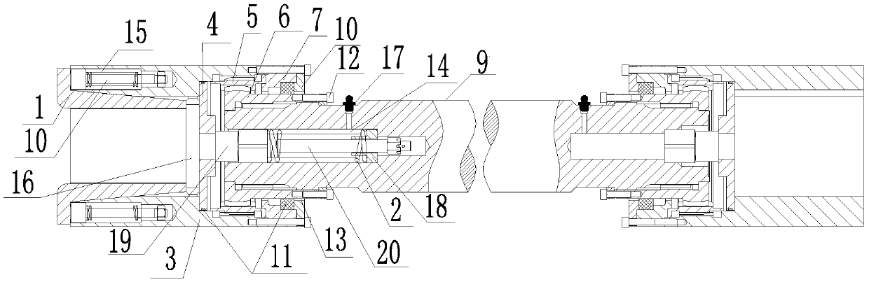
[0018] Such as figure 1 The high stability coupling includes copper brake iron 1, buffer spring 2, connecting flange 3, backing plate 4, transition gear sleeve 5, drum gear sleeve 6, positioning sleeve 7, end cover 8 , the intermediate shaft 9, the spring ejector rod 10 and the seal ring 11, there are two connecting flanges 3, and the two connecting flanges 3 are coaxially distributed, and the connecting flange 3 is an "I"-shaped cavity structure, and the connection method A connecting cavity 31 is set on the front end of the blue 3, and a positioning cavity 32 is set on the rear end. The connecting cavity 31 and the positioning cavity 32 are coaxially distributed and communicated with each other, and the inner diameter of the connecting cavity 31...


PUM


Abstract

The invention relates to a coupler strong in stability. The coupler strong in stability comprises a copper brake, a buffer spring, connection flanges, a cushion plate, a transition gear sleeve, crowngear sleeves, a positioning sleeve, end caps, a middle shaft, a spring ejection rod and a seal ring, wherein the number of the connection flanges is two, the two connection flanges are coaxially distributed, a connection cavity is formed in the front end face of each connection flange, a positioning cavity is formed in the rear end face of each connection flange, the cushion plate abuts against the bottoms of the connection cavities, the transition gear sleeve and the positioning sleeve are each of a closed ring structure distributed coaxial with the connection cavities, each end cap is embedded in the front end face of each connection cavity and connected with the front end face of each corresponding connection flange through a positioning bolt, and two ends of the middle shaft are respectively connected with the connection flanges. The coupler strong in stability can effectively improve structure strength and bearing cavity and effectively improve convenience and efficiency of connection operation on the one hand, and has good structure toughness and can effectively reduce acting force of axial endplay and radial runout, generated during the power transmission process, on the other hand.

Description

technical field [0001] The invention relates to a shaft coupling, in particular to a shaft coupling for a rolling mill. Background technique [0002] In the operation of the rolling mill equipment, it is necessary to connect the rolling mill and the drive motor equipment through a coupling, which requires relatively large power transmission and high power transmission accuracy. However, in actual use, the current rolling mill does not have a dedicated Couplings, the couplings used are often traditional cross couplings and serpentine couplings. Although they can meet the needs of use, on the one hand, there are insufficient structural strength of the coupling, low power transmission efficiency and power On the other hand, the current couplings are prone to axial movement and radial runout during operation, resulting in serious friction loss of the coupling equipment, and are prone to axial movement, radial runout, etc. The jumping force causes the drive shafts of couplings, ...

Claims


Application Information

Patent Timeline
Patent Type & Authority Applications(China)
IPC IPC(8): F16D3/12
CPCF16D3/12
Inventor 马立成
Owner 江苏泰克曼传动设备有限公司
Why Eureka
Try Eureka