Spiral type ventilation structure for oil and gas delivery pipe in permafrost region

An oil and gas pipeline and spiral technology, which is applied in the field of spiral ventilation structure, can solve the problems of not being able to ensure the frozen state of the soil around the pipe, not being able to completely block the heat transfer, and being uneconomical and practical, so as to prevent the occurrence of pipeline diseases, The effect of good application and promotion prospect and simple processing method

Inactive Publication Date: 2019-08-09
LANZHOU JIAOTONG UNIV +1
View PDF9 Cites 1 Cited by
  • Summary
  • Abstract
  • Description
  • Claims
  • Application Information

AI Technical Summary

Problems solved by technology

However, these technical measures have certain limitations. Although the thermal insulation measures reduce the heat dissipation, they cannot completely block the heat transfer and cannot ensure the frozen state of the soil around the pipe.
The hot rod or door type ventilation pipe is arranged at a certain interval along the length of the pipe, and only in the local layout position to cool down the soil around the pipe and control the melting of the soil around the pipe; if the heat rod or door type ventilation pipe is arranged If it is too dense, it will be expensive, especially the hot rod method, which is not economical and practical

Method used


Image

  • Spiral type ventilation structure for oil and gas delivery pipe in permafrost region
  • Spiral type ventilation structure for oil and gas delivery pipe in permafrost region
  • Spiral type ventilation structure for oil and gas delivery pipe in permafrost region

Examples


Embodiment Construction

[0029] The present invention will be described in detail below in conjunction with specific embodiments. The following examples will help those skilled in the art to further understand the present invention, but do not limit the present invention in any form. It should be noted that those skilled in the art can make several modifications and improvements without departing from the concept of the present invention. These all belong to the protection scope of the present invention.

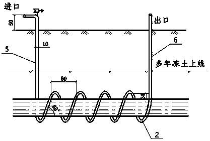
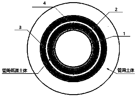
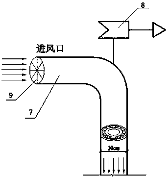
[0030] Such as Figure 1-Figure 5 As shown, the embodiment of the present invention provides a spiral ventilation structure for oil and gas pipelines in permafrost regions. The spiral ventilation structure includes an insulation layer 3 and a spiral ventilation pipe 2 arranged outside the oil and gas pipeline 1. The thermal insulation layer 3 is pasted on the outer wall of the oil and gas pipeline 1, and a bracket 4 is arranged between it and the spiral ventilation pipe 2. The vertical air inlet p...


PUM


Abstract

The invention discloses a spiral type ventilation structure for an oil and gas delivery pipe in a permafrost region. The spiral type ventilation structure comprises an insulating layer arranged on theouter side of the oil and gas delivery pipeline, and a spiral type ventilation pipe. The insulating layer is pasted to the outer wall of the oil and gas delivery pipeline. A support is arranged between the insulating layer and the spiral type ventilation pipe. A vertical air inlet pipe and a vertical air outlet pipe of the oil and gas delivery pipeline extend out of the ground. Through the spiraltype ventilation structure, a frozen soil body around the oil and gas delivery pipeline can be protected effectively, thermal damage to the soil body around the oil and gas delivery pipeline in the permafrost region is avoided, pipeline damage is eliminated, and operation safety of the pipeline in the permafrost region is improved.

Description

technical field [0001] The invention relates to the field of structural design of oil and gas pipelines, in particular to a spiral ventilation structure for oil and gas pipelines in permafrost regions. Background technique [0002] There are rich oil and gas resources in permafrost areas. With the further demand for energy in the development of society, a large number of oil and gas pipeline projects have been built in permafrost areas to develop and transport oil and gas resources. In Alaska of the United States, northern Canada, some Nordic countries and Russia, many oil and gas pipeline projects have been laid in permafrost areas. The well-known oil pipeline project in the permafrost region is the oil pipeline project from Haines, Alaska to Fairbanks built in 1956; in 1977, the Alaska oil pipeline with a length of 1280km began to operate. In 1985, the Roman well oil pipeline located in the discontinuous permafrost area of ​​Canada was successfully laid. In the early 197...

Claims


Application Information

Patent Timeline
Patent Type & Authority Applications(China)
IPC IPC(8): F17D1/20
CPCF17D1/20
Inventor 刘德仁王旭汪鹏飞徐震蒋代军胡渊白鹤王聪
Owner LANZHOU JIAOTONG UNIV
Why Eureka
Try Eureka